Sign In
Upload
Download
Table of Contents
Contents
Add to my manuals
Delete from my manuals
Share
URL of this page:
HTML Link:
Bookmark this page
Add
Manual will be automatically added to "My Manuals"
Print this page
×
Bookmark added
×
Added to my manuals
Manuals
Brands
JPS Manuals
Gateway
Z Series
Optimization manual
JPS Z Series Optimization Manual
Hide thumbs
1
Table Of Contents
2
3
4
5
6
7
8
9
10
page
of
10
Go
/
10
Contents
Table of Contents
Troubleshooting
Bookmarks
Table of Contents
Table of Contents
General
Before You Begin
Jps Channel Profiles
Local Handset And/Or USB Headset
Radio Interface Cables
Jps Radio Interface Cables
Customer-Designed Radio Cables
Audio Adjustments
Receive (Input) Level - (RX Audio Level)
Transmit (Output) Level - (TX Audio Level)
Transmit Delay (TX Audio Delay)
Receive Delay (RX Audio Delay)
Audio Levels and Delays for Virtual or Backhaul Channels
Vox Threshold
Troubleshooting Tips
Symptoms: User in Field Complains of Missed First Syllables
Symptoms: User in Field Complains of Missed Syllables MID-Conversation
Symptoms: Radio Channel Experiencing Continuous Active COR State
Symptoms: Audio Sounds too Weak
Symptoms: Audio Sounds too Loud or Distorted
Symptoms: False Keying of Donor Radio by Radio Channel
Symptoms: Cross-Connected Radios Continuously Key each Other
Advertisement
Quick Links
Download this manual
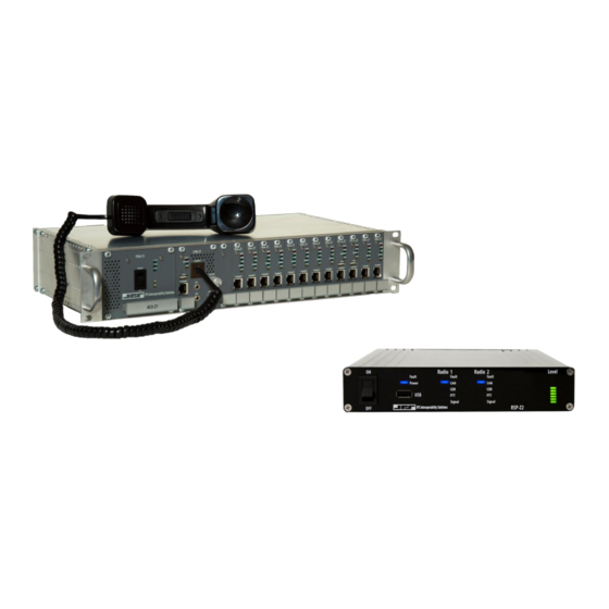
INTEROPERABILITY NOW
Audio Optimization Guide
Z-Series
Devices and Gateways
Designed and Manufactured by:
JPS Interoperability Solutions
5800 Departure Drive
Raleigh, NC 27616
919-790-1011
sales@jpsinterop.com
/
support@jpsinterop.com
www.jpsinterop.com
JPS P/N 2740-500600
Revision 1.0
© March 2021
Table of
Contents
Previous
Page
Next
Page
1
2
3
4
5
Advertisement
Table of Contents
Need help?
Do you have a question about the Z Series and is the answer not in the manual?
Ask a question
Questions and answers
Related Manuals for JPS Z Series
Gateway JPS RSP-Z2 Installation And Operation Manual
Dual channel interoperability gateway (64 pages)
Recording Equipment JPS RSP-Z2 Quick Start Manual
Dual channel analog-ip interface (12 pages)
Gateway JPS RSP-Z2 Quick Start Manual
Dual channel interoperability gateway (9 pages)
Gateway JPS ACU-5000 Installation And Operation Manual
Twelve channel interoperability gateway (86 pages)
Gateway JPS NXU-2B Installation And Operation Manual
Network extension unit (70 pages)
Gateway JPS ACU-Z1 Optimization Manual
(10 pages)
This manual is also suitable for:
Acu-z1
Rsp-z2
Table of Contents
Print
Rename the bookmark
Delete bookmark?
Delete from my manuals?
Login
Sign In
OR
Sign in with Facebook
Sign in with Google
Upload manual
Upload from disk
Upload from URL


Need help?
Do you have a question about the Z Series and is the answer not in the manual?
Questions and answers