Table of Contents
Advertisement
INTEROPERABILITY NOW
Installation and Operation Manual
NXU-2B
Network Extension Unit
JPS Interoperability Solutions
5800 Departure Drive
Raleigh, NC 27616
919-790-1011
Email:
sales@jpsinterop.com
/
support@jpsinterop.com
www.jpsinterop.com
JPS P/N 5190-200200
Revision 1.5
August 2020
Interoperability Now!
Advertisement
Table of Contents
Troubleshooting

Related Manuals for JPS NXU-2B


Summary of Contents for JPS NXU-2B
- Page 1 INTEROPERABILITY NOW Installation and Operation Manual NXU-2B Network Extension Unit JPS Interoperability Solutions 5800 Departure Drive Raleigh, NC 27616 919-790-1011 Email: sales@jpsinterop.com support@jpsinterop.com www.jpsinterop.com JPS P/N 5190-200200 Revision 1.5 August 2020 Interoperability Now!
- Page 2 NXU-2B Operations Manual NOTICE © 2020 JPS Interoperability Solutions. NXU and NXU-2B are trademarks of JPS Interoperability Solutions, Inc. JPS Interoperability Solutions reserves the right to make changes to the equipment and specifications without prior notice. CAUTION Changes and modifications to this equipment not expressly approved by JPS Interoperability Solutions could impair proper operation of the equipment and/or could void user’s warranty.
-
Page 3: Table Of Contents
NXU-2B Operations Manual Table of Contents GENERAL INFORMATION ......................1-1 ............................1-1 COPE ..........................1-1 ESCRIPTION 1.2.1 NXU General ........................1-1 1.2.2 Advantages of NXU Technology ..................1-2 ........................1-2 ETWORK ETAILS ........................1-3 PECIFICATIONS ................1-4 QUIPMENT AND CCESSORIES UPPLIED ................1-4 PTIONAL QUIPMENT UPPLIED NXU-2B NXU-2A............1-5 IFFERENCES... - Page 4 3.3.20 Duplex ..........................3-7 3.3.21 COR Priority ........................3-7 3.3.22 COR Inhibit Time ......................3-7 3.3.23 NXU-2B Dispatch Option ....................3-8 ..................3-9 ONFIGURATION VIA ERIAL 3.4.1 Configuration Using an RS-232 Terminal Program ............3-9 3.4.2 Configuration Mode Command Set ................... 3-9 3.4.3...
- Page 5 Symptom: Radio Channel Experiencing Continuous Active COR State ......6-5 6.3.7 Symptom: Audio Sounds Too Weak..................6-5 6.3.8 Symptom: Audio Sounds Too Loud or Distorted..............6-5 ....................6-6 ROUBLESHOOTING ABLE NXU-2B FIRMWARE UPDATE ....................7-1 NXU-2B F ................7-1 IRMWARE PDATE ROCEDURE NXU-2B FAQ (FREQUENTLY ASKED QUESTIONS) ............8-1 ..........................8-1 ENERAL INDEX .............................9-1 Interoperability Now!
- Page 6 NXU-2B Operations Manual List of Figures 1-1 NXU-2B B ..................1-2 IGURE ASIC LOCK IAGRAM 1-2 T NXU-2B ..........1-7 IGURE NABLING A ADIO EPEATER UNCTION 1-3 NXU-2B P LE D ..... 1-8 IGURE REATES EMOTE ISPATCH APABILITY SING AN...
- Page 7 NXU-2B Operations Manual Glossary Glossary Carrier Operated Relay A signal from a receiver that gives a positive indication that a carrier or signal is being received and that the receiver is unsquelched. It has the same function as Carrier Operated Squelch (COS).
- Page 8 NXU-2B Operations Manual blank page viii...
-
Page 9: General Information
(usually the operator end) is the client. The audio, RS-232, and status bits are transparently transferred between the server and the client. Any NXU-2B can be set up as a server or as a client depending on system needs. The RS-232 interface allows for different baud rates between the server and the client. -
Page 10: Advantages Of Nxu Technology
Ethernet hub or switch using standard CAT 5 twisted pair cable, also known as UTP. The maximum cable length between an NXU-2B and its hub port is 100 meters. With the right connective equipment (recommended or supplied by JPS), the NXU-2B’s Ethernet port can be linked with virtually any LAN, WAN, or the Internet, no matter which topology or cabling system is in use. -
Page 11: Specifications
NXU-2B Operations Manual 1.4 Specifications Table 1-1 Specifications RX Audio Input Input impedance Balanced 47k ohms, transformer coupled, 600 ohm selectable Input Level Incoming signals adjustable from -26 to +10 dBm to set 0 dBm nominal input; +15 dBm clipping. +20 dB boost configurable Frequency Response 10 Hz to 3600 Hz +/- 2dB. -
Page 12: Equipment And Accessories Supplied
Generic Radio Interface Cable; unterminated at radio end; 15 ft. 5961-291115 Interface cables for a very wide range of commercial radios are available for purchase. Email JPS or consult the JPS Interoperability Solutions website for a listing: Email: sales@jpsinterop.com support@jpsinterop.com... -
Page 13: Differences Between The Nxu-2B And The Nxu-2A
(open drain transistor) keying output. There is a jumper selectable solid-state output available on the NXU-2B as well, but the default is to use the relay for PTT. The relay allows for higher keying voltages and currents than the solid-state output. -
Page 14: Nxu-2B Overview
These definitions are essential in understanding the basic operation of an interoperability device, such as a JPS ACU Gateway or this NXU-2B. That is: If multiple communications devices are engaged in an interoperability net, whenever one device detects active COR (valid audio input), that audio, along with a PTT signal, is sent to all other devices in the net to be retransmitted. -
Page 15: Configuration
Figure 1-2 Two NXU-2Bs Enabling a Radio Repeater Function A simple application of the NXU-2B. A pair of the devices are used to connect a pair of radio channels. Note that an Active COR (unsquelched) condition on one of the radios causes its RX audio to be sent via its associated NXU-2B across the network to the other NXU-2B/radio pair. - Page 16 The new JPS “Z” product line of interoperability gateways also includes RoIP interfaces, and therefore the NXU-2B can be used to interface radios and other 2/4 wire devices to them. The ACU-Z1 modular gateway shown in the upper left can make up to 12 local connections using its plug-in modules.
- Page 17 Figure 1-5 Single NXU-2B Connects a Radio Channel to a JPS VIA PTToC Channel Just as its predecessor, the NXU-2A did, the NXU-2B can be used to connect a radio channel to a variety of Push-To-Talk over Cellular (PTToC) applications, including the JPS VIA app.
- Page 18 NXU-2B Operations Manual End of Section One 1-10...
-
Page 19: Installation
Contact the carrier and file a shipment damage claim. A full report of the damage should also be reported to the JPS Customer Service Department. The following information should be included in the report:... -
Page 20: Installation Overview
2. Provide the proper primary power for the unit. 3. Interconnect the unit with the communications system via the NXU-2B's rear panel connectors. The rear panel Audio/Control jack provides the lines necessary to interface the NXU-2B to your audio equipment. -
Page 21: Installation Considerations
The unit is 1.36 inches tall, and 6.5 inches wide by 6.5 inches deep. The NXU-2B must be installed in a structure that provides both protection from the weather and assurance of ambient temperatures between -20 and +60 degrees C. Since the unit is neither splash proof nor corrosion resistant, it must be protected from exposure to salt spray. -
Page 22: Internal Jumper Configuration
NXU-2B Operations Manual 2.5.1 Internal Jumper Configuration The illustration below shows the NXU-2B internal PCB jumper locations. The only reason to open the unit is if the default settings are not optimal for your system. For the majority of applications, the default jumper settings are sufficient and need not be changed. -
Page 23: E&M Return Selection
2.6 Power Requirements The NXU-2B is designed to operate from a nominal +12V DC supply. The unit will meet all of its specifications over a voltage range of +11 to +15 VDC and will be damaged by a DC source that delivers a constant (non-transient) DC voltage above this range. -
Page 24: Rear Panel Connectors
COR and PTT control signals. You do not need this adapter on the NXU-2B, as its audio port has been changed to match that of the ACU product family, and cables designed specifically for the ACU products will work on the NXU-2B. - Page 25 –26 to +10 dBm. 2.8.2.3 COR Input The COR input to the NXU-2B is a high impedance input and can be programmed to be active high or active low. In the active low configuration, the input is pulled up to +5V DC internally through a 47K ohm resistor.
-
Page 26: Network Connection
2.8.4.1 Connecting Equipment and Computers to an NXU-2B A straight-through RS-232 serial cable is used to connect the NXU-2B to a PC serial port. In order to connect the NXU-2B serial port to other serial devices you may need a DB-9 male-male null modem cable, also called a crossover cable. - Page 27 NXU-2B Operations Manual RS232 RS232 Device Straight Device Device Null Device Through Modem LAN, WAN Cable Cable Or T1 COMP NXU-2 NXU-2 ACU-1000 RS232 Device Device Straight Through Cable RS232 Device Null Device Modem Cable RS232 Null Device Device Modem...
- Page 28 NXU-2B Operations Manual End of Section Two 2-10...
-
Page 29: Configuration
If the above network parameters are compatible with your network then you may attach the NXU- 2B to your network and use your web browser to configure the NXU-2B as outlined in the sections that follow. Otherwise configure the computer’s Ethernet port to a static IP address of 192.168.1.xxx (where xxx is a number between 2 and 199) and a subnet mask of 255.255.255.0. -
Page 30: Configuration Via Web Browser
3.3 Configuration via Web Browser Figure 3-1 NXU-2B Configuration Page The simplest way to configure the NXU-2B is to browse to the unit and click on Configuration to open the unit’s Configuration Page as shown above. Configuration parameters are set via dropdown menus, entering a number, or entering text to give the NXU-2B a specific name. -
Page 31: Ip Address And Subnet Mask
3.3.4 Unit is a (Client or Server) Sets this NXU-2B to function either as a Client or as a Server. A Client is able to make or break connections with Servers; Servers can only accept connection requests from a Client. -
Page 32: Command Port
Connectionless mode consists solely of a unicast UDP channel for VoIP traffic (along with the status bits such as PTT and COR) between the NXU-2B and another unit. No serial traffic is exchanged. This mode is reserved for special applications such as the JPS WAIS (Wide Area Interoperability System) and should not be used for day-to-day operation. -
Page 33: Voice Compression
NXU-2B Operations Manual 3.3.9 Voice Compression In order to send voice information over an IP network efficiently the NXU-2B uses digital signal processing algorithms to compress the voice information. Several different voice compression methods are available to support a variety of applications. For example, some compression methods work well with voice and provide a high amount of compression, but do not handle signaling tones very well. -
Page 34: Vox/Vmr Sensitivity
Selecting a value for RX input level means that the NXU-2B expects that level as its nominal input. That is, if the NXU-2B RX Audio Input is set to 0, the unit expects, and operates best, with an input of 0dBm. -
Page 35: Rx Delay
2B will round to the nearest 100mS interval. When additional delay is used, the received audio will be delayed before being sent to the network, relative to when the NXU-2B sends an “Active COR” valid audio signal, which is not delayed. -
Page 36: Nxu-2B Dispatch Option
This setting allows the optional WAIS Dispatch capability to be enabled. This is an extra cost option. Upon purchase, JPS will provide an authentication code which will enable the option when entered. The code will work only for the MAC address it was created for. Clicking on... -
Page 37: Configuration Via Serial Port
NXU-2B Operations Manual 3.4 Configuration via Serial Port The serial port may be used for configuration if it is not practical to configure the NXU-2B via a web browser, or you are more accustomed to using this method. Connect a standard serial cable from a suitable COM port on your PC to the RS-232 connector on the NXU-2B rear panel. -
Page 38: Command Summary
3.4.3 Command Summary This is a full list of the commands available in the NXU-2B command mode. More detail is given on the following pages. You can get a one-line summary of each command by typing HELP followed by the command. - Page 39 SAVE - Save NXU-2B settings to FLASH memory and restart SECURITY <security level> - Set the security level (0-255) SRVRIP <ip address> - Set the IP address of the NXU-2B server SRVRPORT <port number> - Set the port where to send VOIP traffic STAT - Return this client's current connection status STOP <1/2>...
-
Page 40: Setting Unit Ip Address
NXU-2B Operations Manual 3.4.4 Setting Unit IP Address The first thing you should do is to set the IP address of the unit. The NXU-2B comes from the factory with a default IP address set to 192.168.1.200. Set the address by typing: MYIP <IP address>... -
Page 41: Serial Port Settings
COR, while COR 1 selects active high COR sense. COR 2 selects VOX mode. In VOX mode, no connection to the NXU-2B COR input is required, since the audio input level itself is used to determine when a signal is present. COR 3 selects VMR (Voice Modulation Recognition) mode. -
Page 42: Vox Hang Time
2000, 3000, or 4000 to select the hang time. The factory default is 500 milliseconds. 3.4.13 COR Inhibit Time In some applications it may be necessary to inhibit the NXU-2B’s response to the COR input (whether hardwired COR or VOX) for a brief period of time (and under certain circumstances) in order to avoid problems with the “ping pong”... -
Page 43: Security Settings
It cannot be changed by the user. 3.4.17 Command Port The port used by the NXU-2B for receiving commands via the telnet protocol or from a WAIS Controller. The value defaults to 23 and under normal circumstances should not need to be changed. -
Page 44: Input Level Boost +20Db
(mS)’ field, the user may introduce up to5 seconds of delay, in specified in 1 mS increments. Upon editing the field with numeric data, the NXU-2B will round to the nearest 100mS interval. When additional delay is used, the PTT\ signal will be asserted prior to the delayed audio being presented, allowing LMR trunking systems to be accessed without audio loss. -
Page 45: Communications Mode
Connectionless mode consists solely of a unicast UDP channel for VoIP traffic (along with the status bits such as PTT and COR) between the NXU-2B and another unit. No serial traffic is exchanged. This mode is reserved for special applications such as the JPS WAIS (Wide Area Interoperability System) and should not be used for day-to-day operation. -
Page 46: Store Setup Changes With Save Command
After any configuration changes have been made, SAVE must be typed in order to store the new settings in memory. The NXU-2B will automatically restart after changes have been saved. If you do not make any changes and want to return the serial port to the data mode, type TRAN to place the serial port in transparent mode. -
Page 47: Operation
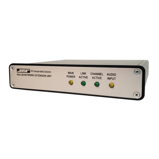
The green Link Active LED is illuminated whenever the NXU-2B has an IP connection open to another NXU-2B on the network. If this indicator is not lit, either the NXU-2B does not have an active VoIP connection or the connection has been lost. -
Page 48: Operation At Power-Up
Selecting a value for RX input level means that the NXU-2B expects that level as its nominal input. That is, if the NXU-2B RX Audio Input is set to 0, the unit expects, and operates best, with an input of 0dBm. Likewise, selecting a value for the TX output level means that the NXU-2B will produce that level as its nominal output level, assuming that the remote NXU-2B (or other linked RoIP device) has its audio input configured correctly. -
Page 49: Auxiliary I/O
Command Mode. 4.4.5 Auxiliary I/O The NXU-2B has two sets of independent inputs and outputs that may be used for control of the user’s equipment. AUX IN 0 and AUX IN 1 are active-low inputs which, when activated on one end, will cause AUX OUT 0 and AUX OUT 1 on the other end to become active. -
Page 50: Serial Or Telnet Connection Control
The status of these commands may be viewed by typing: STAT STAT returns the following responses: CON <IP address> The unit is connected to an NXU-2B at address <IP address> The unit is not connected ATT <IP address> The unit is attempting a connection to <IP address>... -
Page 51: Security
NXU-2B. 5.1.1 Password Setting The NXU-2B may be set to require a username and password for HTTP (web) access and for firmware updating. The default setting requires no username or password. To program a username and password, browse to the NXU-2B IP address and select the Security link. - Page 52 NXU-2B Operations Manual When the NXU-2B is programmed to require a username and password, any attempt to access the unit via HTTP will result in the web browser displaying the following dialog: Figure 5-2 Network Password Dialog In order to access the NXU-2B you must enter the Administrator username and password that was previously programmed using a web browser.
-
Page 53: Nxu-2B Field Optimization Guide
JPS equipment in tandem with the cable. Just as importantly, it lists any radio programming, or switch/level/jumper plug settings required at the radio for proper operation. JPS cables are always the best option for interfacing a radio to the NXU-2B or other JPS equipment. 6.1 Radio Interface Using JPS Custom Radio Cables This section will assume that a JPS radio interface cable is used. -
Page 54: Rx Audio Input Level
Input Level should be set to -12dB. This must be understood to know which way to change the audio level for proper operation. If the NXU-2B, when set to -12 dB, is not receiving enough audio, the value must be set to a lower number to correspond to the actual input level. -
Page 55: Rx Audio Delay
Unterminated Radio Cable, JPS P/N 5961-291115. This shielded cable includes the D15 end of the cable that plugs directly into the NXU-2B rear analog port, along with the small PCB found in other JPS cables – this circuitry has a variety of variable attenuating, terminating and DC-blocking components;... -
Page 56: Radio Interface Troubleshooting Tips
Active COR signal for a short time after the channel ends a PTT session. Watch the Channel Active LED on the NXU-2B panel and increase the COR Inhibit time until the Channel Active LED no longer flashes at the cessation of PTT. -
Page 57: Symptom: False Keying Of Donor Radio By Radio Channel
Cause: Received audio level from donor radio (or other device type) is too low Solution: Lower RX INPUT LEVEL until NXU-2B Audio Input LED flashes with voice peaks Cause: Transmit audio level delivered to donor radio is too low (verify/rectify cause above first!) Solution: Increase TX OUTPUT LEVEL until donor radio is properly modulated. -
Page 58: Troubleshooting Table
Verify that the Server’s IP address has been programmed into the Client using SRVRIP command. The port used by the NXU-2B for receiving audio from the network has a default value of 1221. Under normal circumstances, there is no reason to change. If necessary, it can be changed using the PORT command. - Page 59 CHANNEL ACTIVE indicator is on continuously. Verify that the COR polarity is programmed properly. See section 3.3.8. If NXU-2B is attached to a radio COR line, make sure the radio squelch is set properly. Audio has pauses and/or gaps in it.
- Page 60 NXU-2B Operations Manual End of Section Six...
-
Page 61: Nxu-2B Firmware Update
JPS web page at http://www.jpsinterop.com To update the NXU-2B firmware you will need to access the NXU-2B via a web browser. Browse to the IP address of the NXU-2B and select the Information link. From the Information page select the Security link. - Page 62 NXU-2B Operations Manual End of Section Seven...
-
Page 63: Nxu-2B Faq (Frequently Asked Questions)
COR is usually obtained from a radio and indicates that a signal is being received. If you do not have a COR line, or a line that performs this function, then you can either tie the NXU-2B COR line to its active state or you can use VOX mode. VOX mode is preferred since enabling COR permanently will cause data to flow continuously across the link, even if no audio is present. - Page 64 NXU-2B Operations Manual After losing power on one end of an NXU-2B link, it takes a while for the units to re- establish communications. Why is this? The NXU-2B will wait up to 20 seconds before determining that the link has been disconnected.
- Page 65 (or with the cooperation of) the network administrator. This will allow TCP and UDP packets through the firewall so they can be received by the server unit. There is no security risk in doing this since the NXU-2B cannot be made to access files or forward information to or from other systems.
- Page 66 Should I use NAT with the NXU-2B? The only time it is advisable to use NAT with the NXU-2B is when you wish to have multiple units on a network, but have only one public IP address. An example of this would be a bank of NXU-2Bs sharing a broadband type connection such as DSL or cable modem where only one IP address is allocated by your ISP.
- Page 67 24, 32, and 64 Kbps vocoders. In general data should be sent via the RS-232 port. I've connected my radio to the NXU-2B, I have the levels turned all the way up, and can still barely hear the audio. What's wrong? The NXU-2B uses balanced audio on the input.
- Page 68 NXU-2B Operations Manual End of Section Eight...
-
Page 69: Index
9 Index 10/100BASE-T Ethernet ......1-2 Factory Defaults ........3-16 Front & Rear Views ........ 2-3 Front Panel ..........4-1 Address ..........2-1 Audio Input ..........2-7 Audio Output .......... 2-7 General Information ........ 1-1 AUX Inputs ..........2-7 Glossary ........... vii AUX Outputs .......... - Page 70 NXU-2B Operations Manual Security ........... 4-4 UDP ............vii Security Settings ........3-15 Unpacking and Inspection....... 2-1 Serial Control .......... 4-3 Serial Port Configuration ......3-9 VMR ............. 3-16 Serial Port Settings ....... 3-13 Voice Compression Settings ....3-14 Setting Unit IP Address ......3-12 VoIP ............
Need help?
Do you have a question about the NXU-2B and is the answer not in the manual?
Questions and answers