
Related Manuals for KitchenAid Whirlpool W11400254


Summary of Contents for KitchenAid Whirlpool W11400254
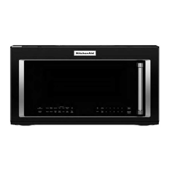
- Page 1 https://appliancetechmanuals.com Multimedia Enhanced SERVICE MANUAL Microwave Hood Combination W11400254...
- Page 2 https://appliancetechmanuals.com FOREWORD This Whirlpool® Service Manual (Part No. W11400254), provides the In-Home Service Professional with service information for the “Microwave Hood Combination.” The Wiring Diagram used in this Service Manual is typical and should be used for training purposes only. Always use the Wiring Diagram supplied with the product tech sheet when servicing the oven.
-
Page 3: Table Of Contents
https://appliancetechmanuals.com TABLE OF CONTENTS Microwave Hood Combination SECTION 1: GENERAL INFORMATION ................1-01 MICROWAVE HOOD COMBINATION SAFETY ................... 1-02 PRODUCT SPECIFICATIONS ....................... 1-03 MODEL & SERIAL NUMBER LOCATION ..................... 1-11 MODEL NOMENCLATURE ......................... 1-12 TECH SHEET LOCATION ........................1-16 SECTION 2: DIAGNOSTICS ..................2-01 SAFETY .............................. - Page 4 https://appliancetechmanuals.com NOTES...
-
Page 5: Section 1: General Information
https://appliancetechmanuals.com GENERAL INFORMATION Section 1: General Information This section provides general safety, parts, and information for the “Microwave Hood Combination.” ■ Microwave Hood Combination Safety ■ Product Specifications ■ Model & Serial Label Location • • Model Nomenclature ■ Tech Sheet Location Microwave Hood Combination... -
Page 6: Microwave Hood Combination Safety
https://appliancetechmanuals.com GENERAL INFORMATION (Cont.) Microwave Hood Combination Safety Your safety and the safety of others are very important. We have provided many important safety messages in this manual and on your appliance. Always read and obey all safety messages. This is the safety alert symbol. This symbol alerts you to potential hazards that can kill or hurt you and others. -
Page 7: Product Specifications
https://appliancetechmanuals.com GENERAL INFORMATION (Cont.) Product Specifications Whirlpool® Microwave Hood Combination Dimensions Capacity (Cu. Ft.) 1.7 or 2.1 Cutout Width (IN, inches) Depth Closed Excluding Handles (IN, inches) or 16 or 16 Depth Closed Including Handles (IN, inches) Depth With Door Open 90 Degree (IN, inches) or 50 Depth (IN, inches) or 17... - Page 8 Ventilation Type Downdraft or Updraft Venting Exterior or Recirculating Electrical Amps 15 or 20 Volts KitchenAid® Microwave Hood Combination Dimensions Capacity (Cu. Ft.) 1.9 or 2 Depth With Door Open 90 Degree (IN, inches) or 44 Depth (IN, inches) or 17...
- Page 9 https://appliancetechmanuals.com GENERAL INFORMATION (Cont.) Description Microwave Type Over-the-Range Size (IN, inches) Exterior Cabinet Color Black Door Release Handle Left Door Swing Handle Color Stainless Steel Controls Control Location Right or Bottom Control Type Electronic Touch Display Color White Electronic Display Type Scrolling Electronic Display Features Number of Power Levels...
- Page 10 https://appliancetechmanuals.com GENERAL INFORMATION (Cont.) JennAir® Microwave Hood Combination Dimensions Capacity (Cu. Ft.) 1.9 or 2 Depth (IN, inches) Height (IN, inches) Width (IN, inches) or 30 Microwave Details Cooking Power (watts) 900 or 1000 Convection Convection Power (watts) 1600 Interior Light Halogen or Incandescent Number or Racks 1 or 2...
- Page 11 https://appliancetechmanuals.com GENERAL INFORMATION (Cont.) Amana® Microwave Hood Combination Dimensions Capacity (Cu. Ft.) 1.6 or 2 Depth (IN, inches) or 17 or 18 Height (IN, inches) or 17 or 17 Width (IN, inches) Depth Closed Excluding Handles (IN, inches) or 16 Depth Closed Including Handles (IN, inches) Depth With Door Open 90 Degree (IN, inches) Cutout Height (IN, inches)
- Page 12 https://appliancetechmanuals.com GENERAL INFORMATION (Cont.) Microwave Selections Add 30 Seconds, Add A Minute, Control Lock, Cook Power, Cook Time, Cook/Start, Defrost, End of Cycle Signal, Fresh Vegetable, Frozen Entree, Frozen Vegetable, More - Less Function, Off/ Cancel, Pause, Pizza, Popcorn, Potato, Reheat, Scale, Soften/Melt, Stage Cooking, Steam, Timer Ventilation System Blower Type...
- Page 13 https://appliancetechmanuals.com GENERAL INFORMATION (Cont.) Exterior Cabinet Color Black or Stainless Door Release Handle Left Door Swing Handle Color Black or Stainless Steel Controls Control Location Right Control Type Electronic Touch Display Color Amber Electronic Display Type Digital Number of Keypads 14 or 22 Number of Quick Touch/One-Touch Selections Scrolling Electronic Display...
- Page 14 https://appliancetechmanuals.com GENERAL INFORMATION (Cont.) Ikea® Microwave Hood Combination Dimensions Capacity (Cu. Ft.) Depth With Door Open 90 Degree (IN, inches) Depth (IN, inches) Height (IN, inches) Width (IN, inches) Microwave Details Cavity Finish Powder Coat Cooking Power (watts) Interior Light Incandescent Work Surface Light Incandescent...
-
Page 15: Model & Serial Number Location
https://appliancetechmanuals.com GENERAL INFORMATION (Cont.) Model & Serial Number Location Model & Serial Number Label Location (behind door) Microwave Hood Combination 1-11... -
Page 16: Model Nomenclature
https://appliancetechmanuals.com GENERAL INFORMATION (Cont.) Model Nomenclature Whirlpool® Model Nomenclature MODEL NUMBER Brand W = Whirlpool Platform M = Microwave O = Wall Oven Sub Platform/Fuel C = Countertop (Microwave) H = Microwave Hood Combo B = Built-In (Microwave) D = Drawer (Microwave) Series 1 = OPP 3 = Low Line... - Page 17 GENERAL INFORMATION (Cont.) KitchenAid® Model Nomenclature MODEL NUMBER Brand K = KitchenAid Categories C = Cooktop O = Wall oven F = Freestanding Range S = Slide-In Range M = Microwave Oven Configuration/Fuel B = Built-in C = Countertop...
- Page 18 https://appliancetechmanuals.com GENERAL INFORMATION (Cont.) Amana® Model Nomenclature MODEL NUMBER Brand A = Amana Platform Type MV = Over the Range Micro MC = Countertop Micro Suite Series 2 = Basic / OPP / Contract 4 = 3 Piece 6 = 2 Piece Sensor 3 = Non-Sensor 5 = Sensor...
- Page 19 https://appliancetechmanuals.com GENERAL INFORMATION (Cont.) Maytag® Model Nomenclature 4205 - 6190 MODEL NUMBER Country Y = Canada Brand M = Maytag Product Type MV = Microwave/Vent Feature Pack Year D = 2014 E = 2015 F = 2016 Color S = Stainless Steel H = White E = Black Microwave Hood Combination...
-
Page 20: Tech Sheet Location
https://appliancetechmanuals.com GENERAL INFORMATION (Cont.) Tech Sheet Location A�er the vent grid 1-16 Microwave Hood Combination... -
Page 21: Section 2: Diagnostics
https://appliancetechmanuals.com DIAGNOSTICS Section 2: Diagnostics This section provides diagnostic and fault codes information for the “Microwave Hood Combination.” ■ Safety ■ Diagnostics ■ Error Codes Microwave Hood Combination... -
Page 22: Safety
https://appliancetechmanuals.com DIAGNOSTICS (Cont.) For Service Technician Use Only Safety DANGER WARNING Electrical Shock Hazard Electrical Shock Hazard Only authorized technicians should perform Disconnect power before servicing. diagnostic voltage measurements. Replace all parts and panels before operating. After performing voltage measurements, Failure to do so can result in death or disconnect power before servicing. -
Page 23: Diagnostics - Touch Panel
https://appliancetechmanuals.com DIAGNOSTICS (Cont.) For Service Technician Use Only Diagnostics - Touch Panel Touch Panel and ACU PCBA Test The microwave hood combination is provided with a self-diagnostic routine that can be accessed through the touch keypad. To initiate this routine: 3. -
Page 24: Error/Failure Codes Indications
https://appliancetechmanuals.com DIAGNOSTICS (Cont.) For Service Technician Use Only Key Name Function Display Buzzer Key Name Function Display Buzzer Cooling Fan On Cavity Lamp 1 beep Hood (Cooktop) 1 beep Hood Fan HIGH Light On (Night)— Relay Cavity Light Key 33 Key 40 4912 and Turntable... - Page 25 https://appliancetechmanuals.com DIAGNOSTICS (Cont.) For Service Technician Use Only Display Likely Failure Recommended Repair Procedure Condition F4E1 Cavity 1. Enter the Diagnostics mode (press CANCEL -CANCEL - START), and then press CONVECT to display the cavity temperature sensor reading. Verify the sensor temperature reading is at temperature room temperature (typically 50°F to 90°F [10°C to 32°C]) and verify failure code.
- Page 26 https://appliancetechmanuals.com DIAGNOSTICS (Cont.) For Service Technician Use Only Display Likely Failure Recommended Repair Procedure Condition F8E5 Exhaust air 1. Enter the Diagnostics mode (press CANCEL -CANCEL - START), and then press WARM HOLD to display the HF NTC thermistor reading. Verify the temperature reading is at room temperature detection temperature (typically 50°F to 90°F [10°C to 32°C]) and verify failure code.
- Page 27 https://appliancetechmanuals.com DIAGNOSTICS (Cont.) For Service Technician Use Only NOTES: n n These diagrams are not intended to show a complete circuit; they represent the position of switches during “DOOR OPEN” or These diagrams are not intended to show a complete circuit; they represent the position of switches during “DOOR OPEN” or “DOOR CLOSED”...
- Page 28 https://appliancetechmanuals.com DIAGNOSTICS (Cont.) For Service Technician Use Only MW Oven Plugged In—Sitting Idle—ACV Readings Brown P1-1 (L) P1-3 (N) White P2-1 (NFS) White P2-2 (Door) Orange P2-3 (N) Green Blue P2-4 (N) P4-1 (FC-V) Blue P4-2 (TT) P4-3 (CL) Green P4-4 (HL) Yellow Black...
-
Page 29: Section 3: Component Testing
https://appliancetechmanuals.com COMPONENT TESTING Section 3: Component Testing This section provides the wiring diagram, component testing, and component location for the “Microwave Hood Combination.” ■ Safety ■ Wiring Diagram ■ Component Testing ■ Component Location Microwave Hood Combination... - Page 30 https://appliancetechmanuals.com COMPONENT TESTING (Cont.) For Service Technician Use Only Safety DANGER WARNING Electrical Shock Hazard Electrical Shock Hazard Only authorized technicians should perform Disconnect power before servicing. diagnostic voltage measurements. Replace all parts and panels before operating. After performing voltage measurements, Failure to do so can result in death or disconnect power before servicing.
- Page 31 https://appliancetechmanuals.com Secondary Magnetron AC Line Filter Board Interlock Switch Thermostat High-Voltage N-In N-Out Components Magnetron Red Tube Black Tube P6-3 P6-5 Monitor White Interlock Switch Golden H.V. P6-2 P6-1 Capacitor Main Fuse Primary H.V. Interlock Diode Switch H.V. Transformer L-In L-Out Cavity Thermostat...
- Page 32 https://appliancetechmanuals.com Cavity Magnetron Secondary Thermostat Interlock Thermostat High-Voltage Switch Components Magnetron Red Tube Black Tube Monitor White Interlock White Switch Golden Golden H.V. Capacitor Fuse Primary H.V. Interlock 20AMP Diode H.V. Switch Transformer AC Line Filter Door Interlock Switch DOOR HF relay 4911 HF relay...
- Page 33 https://appliancetechmanuals.com...
- Page 34 https://appliancetechmanuals.com Cavity Magnetron Secondary Thermostat Interlock Thermostat High-Voltage Switch Components Magnetron Red Tube Black Tube Monitor Interlock White White Switch Golden Golden H.V. Capacitor Fuse Primary H.V. Interlock 20AMP Diode H.V. Switch Transformer AC Line Filter Door Interlock Switch DOOR HF relay 4911 HF relay...
- Page 35 https://appliancetechmanuals.com Magnetron Cavity Secondary Thermostat Thermostat Interlock Switch High-Voltage Components P5-2 Magnetron Red Tube P5-4 Black Tube Monitor White Interlock Switch White Golden P5-1 H.V. Golden Capacitor P5-5 Primary H.V. Fuse Interlock Diode 20AMP Switch H.V. Transformer Door AC Line Filter Interlock Switch Door...
- Page 36 https://appliancetechmanuals.com High-Voltage Components...
-
Page 37: Component Testing
https://appliancetechmanuals.com COMPONENT TESTING (Cont.) For Service Technician Use Only Component Testing IMPOR TANT: Unplug microwave oven or disconnect power. Conduct a microwave energy test after performing any tests or repairs to the microwave oven. Discharge the high-voltage capacitor and remove the lead wires from the primary winding of the high-voltage transformer before Check that all wire leads are in the correct positions before conducting any of the following tests. - Page 38 https://appliancetechmanuals.com COMPONENT TESTING (Cont.) For Service Technician Use Only Components Test/Results 1. Unplug microwave oven or disconnect power. Hood Exhaust Fan Motor 2. Remove wire leads. 3. Measure resistance: n High Speed—Normal: Red (RD) and Blue (BU) wires: 70 to 100 ohms (approximate); Blue (BU) and Black (BK) wires: 30 to 60 ohms (approximate) n Low Speed—Normal: Red (RD) and Blue (BU) wires: 70 to 100 ohms (approximate);...
- Page 39 https://appliancetechmanuals.com COMPONENT TESTING (Cont.) For Service Technician Use Only Components Test/Results 1. Unplug microwave oven or disconnect power. AC Line Filter 2. Remove wire leads. 3. Measure resistance: n Normal: 1-3 (coil): Less than 1 ohm; 2-4 (coil): Less than 1 ohm; 3-4 (resistor): 550 k-800 k ohms n Abnormal: Infinite POWER OUTPUT MEASUREMENT...
-
Page 40: Component Location (Not To Scale)
https://appliancetechmanuals.com COMPONENT TESTING (Cont.) For Service Technician Use Only Component Location (Not to Scale) U S T A. Quartz grill heater (2) U. Monitor interlock switch B. Hood fan motor assembly V. Primary interlock switch C. FC thermistor W. POPCORN PCBA D. -
Page 41: Section 4: Component Access
https://appliancetechmanuals.com COMPONENT ACCESS Section 4: Component Access Multimedia This section provides service parts access, removal, and replacement instructions for the “Microwave Hood Enhanced Combination.” n Accessing the Control Panel n Door Removal n Outer Wrapper Removal n Component Locations Video Available Look for this ICON throughout Section 4 Microwave Hood Combination... -
Page 42: Accessing The Control Panel
https://appliancetechmanuals.com COMPONENT ACCESS (Cont.) Accessing the Control Panel 3. Remove the Phillips head screw at the top of the control WARNING panel. Electrical Shock Hazard Disconnect power before servicing. Replace all parts and panels before operating. Failure to do so can result in death or electrical shock. -
Page 43: Door Removal
https://appliancetechmanuals.com COMPONENT ACCESS (Cont.) Door Removal Outer Wrapper Removal WARNING WARNING Electrical Shock Hazard Electrical Shock Hazard Disconnect power before servicing. Disconnect power before servicing. Replace all parts and panels before operating. Replace all parts and panels before operating. Failure to do so can result in death or Failure to do so can result in death or electrical shock. -
Page 44: Component Locations
https://appliancetechmanuals.com COMPONENT ACCESS (Cont.) Component Locations WARNING Electrical Shock Hazard Disconnect power before servicing. Replace all parts and panels before operating. Failure to do so can result in death or electrical shock. A. Upper Interlock switch holder and switches B. Cooling Fan Motor C. - Page 45 https://appliancetechmanuals.com COMPONENT ACCESS A.Turntable Motor A. Hood Fan Motor Assembly A. Carbon Filter C. Cavity Light A. Hood Fan Motor Adjustment B. Cavity Light Cover D. Cavity Light Holder Screw Locations A. Grease Filter B. Hood (Cooktop) Light Microwave Hood Combination...
- Page 46 https://appliancetechmanuals.com PRODUCT SPECIFICATIONS & WARRANTY INFORMATION SOURCES IN THE UNITED STATES: FOR PRODUCT SPECIFICATIONS AND WARRANTY INFORMATION CALL: FOR WHIRLPOOL PRODUCTS: 1-800-253-1301 FOR TECHNICAL ASSISTANCE WHILE AT THE CUSTOMER’S HOME CALL: THE TECHNICAL ASSISTANCE LINE: 1-800-832-7174 HAVE YOUR STORE NUMBER READY TO IDENTIFY YOU AS AN AUTHORIZED IN-HOME SERVICE PROFESSIONAL FOR LITERATURE ORDERS (CUSTOMER EXPERIENCE CENTER): PHONE: 1-800-851-4605...
- Page 47 https://appliancetechmanuals.com...
Need help?
Do you have a question about the Whirlpool W11400254 and is the answer not in the manual?
Questions and answers