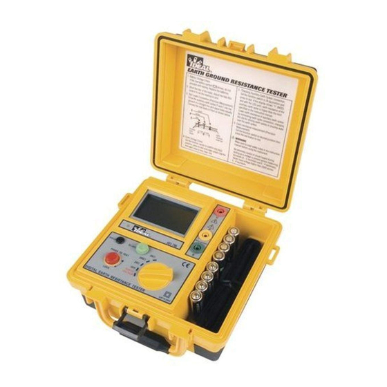
Table of Contents
Advertisement
Quick Links
IDEAL INDUSTRIES, INC.
TECHNICAL MANUAL
MODEL: 61-796
The Service Information provides the following information:
• Precautions and safety information
• Specifications
• Performance test procedure
• Calibration and calibration adjustment procedure
• Basic maintenance (Disassembly, Troubleshooting, Spare Parts list)
Form number: TM61796
Revision: 2. Date: May 2008
Form number TM61796
Rev 2 May 2008
Advertisement
Table of Contents

Subscribe to Our Youtube Channel
Summary of Contents for IDEAL INDUSTRIES 61-796
- Page 1 IDEAL INDUSTRIES, INC. TECHNICAL MANUAL MODEL: 61-796 The Service Information provides the following information: • Precautions and safety information • Specifications • Performance test procedure • Calibration and calibration adjustment procedure • Basic maintenance (Disassembly, Troubleshooting, Spare Parts list) Form number: TM61796 Revision: 2.
-
Page 2: Table Of Contents
TABLE OF CONTENTS Title Page Introduction Precautions and Safety Information Symbols Safety Information Specifications General Specification Ground Resistance Specifications Ground Voltage Potential Specifications Required Standards and Equipment Performance Verifications Battery Test Frequency Test Resistance Test AC Voltage Test Disassembly and Setup For Calibration Calibration Procedure Calibration Verification Test... -
Page 3: Introduction
The information provided in this document is for the use of qualified personnel only. Caution The 61-796 Three Pole Ground Resistance Tester contains parts that can be damaged by static discharge. Follow the standard practices for handling static sensitive devices. -
Page 4: Specifications
Page 2 General Specifications Characteristics Description Display LCD 3 ½ with 2000 counts, maximum display count of 1999 Over-range Indication “1” in the Most Significant Digit (MSD) Operation Frequency of Ω current 820Hz to 1.6kHz at approx. 2mA. Earth Resistance Range 20Ω/200Ω/2000Ω... -
Page 5: Required Standards And Equipment
Precision AC voltage source with a range of 0 to 200V AC @60Hz with an accuracy of .25% or better. • To test the performance of the 61-796, you will need a set of fixed standard resistors with an accuracy of 0.5% or better. Values required are 1Ω, 10Ω, 100Ω, and 1000Ω. -
Page 6: Ac Voltage Test
Set the precision AC power source to standby with an output of 100V @ 60 Hz. • Connect terminals E and P of the 61-796 to the output of the AC source. (C should be left open.) • Energize the AC source. -
Page 7: Calibration Verification Test
Page 5 Ω Adjustment (refer to Figure 2) Connect the 61-796 to the standard resistors as described in the performance test section, Figure 1. Select 20Ω Range. • Short E, P, and C together, adjust 0Ω adj dial for 0.00 ±0.01 ohms on the LCD display. -
Page 8: Calibration Adjustment Locations
Page 6 Calibration Adjustment Locations VR6 ADJUST ACV VR1 ADJUST Hz VR3 ADJUST 10Ω VR4 ADJUST 100Ω VR5 ADJUST 1000Ω Figure 2 Form number TM61796 Rev 2 May 2008... -
Page 9: Component Layout
Page 7 Figure 3 Form number TM61796 Rev 2 May 2008... -
Page 10: Troubleshooting
Page 8 Troubleshooting Symptoms Possible Causes Remedies The LCD has no display No batteries Install the batteries Faulty battery polarity Install the batteries in correct polarity Battery terminal oxidized Replace new battery terminal Wire broken Solder wire Q1 or Q8 broken Replace Q1 (IC-7809FA) or Q8 (IC- 78L05) Poor contact of battery... -
Page 11: Spare Parts List
Page 9 Spare Parts List Description Parts No. Qty. Note Nameplate UP-cover Function switch Test button Hold button 0 Ω adjust Housing case Protection cover Battery Battery case Handle Latch Others Test leads 1 Kit Simplified measurement probe Auxiliary earth spikes Shoulder belt Instruction manual Form number TM61796...


Need help?
Do you have a question about the 61-796 and is the answer not in the manual?
Questions and answers