Table of Contents
Advertisement
Quick Links
Advertisement
Table of Contents

Related Manuals for Topp Music Gear TD-500.4 DSP


Summary of Contents for Topp Music Gear TD-500.4 DSP
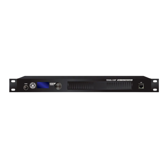
- Page 1 TD-500.4 DSP SWITCHING POWER PROFESSIONAL AMPLIFIER...
-
Page 3: Table Of Contents
1. INTRODUCTION 2. FEATURES 3. USEFULL DATA 4. CONTROL ELEMENT 5. APPLICATIONS 6. WIRING CONNECTIONS 7. BLOCK DIAGRAM 8. TECHNICAL SPECIFICATIONS 9. GUARANTEE 10. NOTES... -
Page 4: Introduction
Introduction Thank you for choosing TOPP PRO. The product switching power professional Amplifier is designed for professional use on stage. The high-quality components and the carefully designed circuits ensure excellent audio performance and an extremely linear frequency response. In fact, the switching technology offers, together with an increased efficiency and a better control of heat dissipation than conventional power supply systems, a drastic reduction of dimensions and weight, for easier transportation and installation. -
Page 5: Control Element
Control Element FRONT PANEL Power Switch It switches ON/OFF the unit main power. OLED Display OLED is used to operate with the encoder. Encoder The encoder is used to control the parameters of amplifier. Air Intake Vents Employ a variable speed internal cooling fan to intake the air through front grill to keep it running cool even under extreme operating conditions. - Page 6 Connect the amplifier to your speaker using these speaker jacks. BREAKER The breaker will break when the amplifier cost too much power or the amplifier is broken. AC POWER Use it to connect your TD-500.4 DSP to the supplied AC cord.
-
Page 7: Applications
Applications Stereo Operation The amplifier can be used in the stereo mode as two separate 1000 watt units, each capable of driving loads down to 4 ohms. Each channel operates independently and has its own input connectors, sensitivity level controls, automatic limiter, fault protection circuitry, power amp, and speaker outputs. - Page 8 Applications Mono Bridge Operation The two internal power amplifiers (CHA and CHB or CHC and CHD) can be bridged together to form a single, higher powered amp. This is especially useful when using the amplifier to power a subwoofer. In the mono mode, the amplifier uses the channel A or C input jacks and sensitivity control(channel B and D's are disabled).
- Page 9 Applications Composing with ARRAY SYSTEM Please load the satellite's preset of the amplifier first. SIG 1 SIG 2 SATELLITE SATELLITE SUBWOOFER SUBWOOFER...
-
Page 10: Wiring Connections
Wiring Connections Ring=Right Signal Sleeve Ring Strain Clamp Tip=Left Signal Sleeve=Ground/Screen Use for Headphone 1/4" Stereo (TRS) Jack Plug Sleeve Tip=Signal Strain Clamp Sleeve=Ground/Screen Use for Mono Line In, Mono 1/4"Jack Plugs 1/4" Mono (TS) Jack Plug Ring=Return Signal Sleeve Ring Strain Clamp Tip=Send Signal... - Page 11 Wiring Connections Ring=Return Signal (Connected together) To Channel Insert Sleeve=Ground/Screen Tip=Signal To Tape or FX Input Sleeve=Ground/Screen 'Tapped' Connection Direct Output Lead (Enables the Insert to be used as a Direct Output while maintaining the channel signal flow) To Processor Input Sleeve=Ground/Screen Tip=Send Signal To Channel Insert...
-
Page 12: Block Diagram
Block Diagram... -
Page 13: Technical Specifications
Technical Specifications Power Specifications(tolerance +/-5%) TD-500.4 DSP 4 ohms(RMS) 500W x 4 Stereo Mode (Both Channels Drive) 8 ohms(RMS) 250W x 4 Bridge Mono Mode 8 ohms(RMS) 1000W x 2 Electrical Specification Input Sensitivity (Limit Off) 0.9-1.1V(0+/-1dBv) Input Impedance 20k ohms balanced or 10k Ohms unbalanced... -
Page 14: Guarantee
Guarantee... -
Page 15: Notes
TD-500.4 DSP... - Page 29 NF05221-1.0...
Need help?
Do you have a question about the TD-500.4 DSP and is the answer not in the manual?
Questions and answers