Table of Contents
Advertisement
Advertisement
Table of Contents

Related Manuals for Topp Music Gear DM24.8


Summary of Contents for Topp Music Gear DM24.8
- Page 1 DM24.8 24 mic preamplifiers with dedicated trim control...
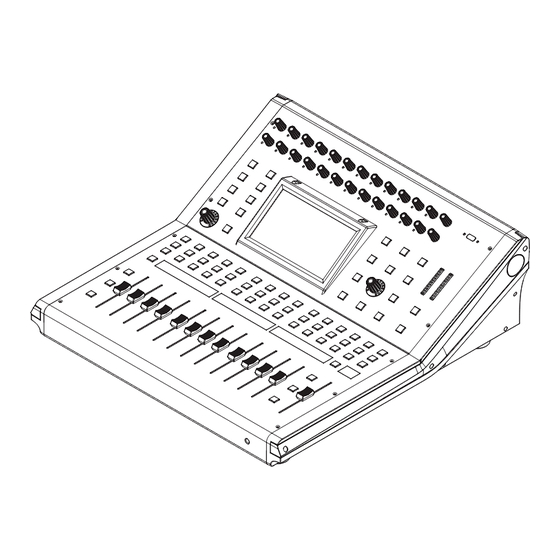
- Page 3 Index front Panel Page7: 1. Ch1-24 input gain control knob 6. Digital In/Out 9. Assign Page8: 7. Automix 13. Channel Page9: 10. Gate Page10: 14. FX Edit 17. System Page11: 18. Save/Load 22. Adjust Parameter Knob Page12: 23. Solo 30. Name Page13: 31.
- Page 4 Index Rear Panel Page15: 1. MIC Input Jack 7. Main Output Page16: 8. Ctrl Out 11. Power Switch under the EM disturbance, the ratio of signal-noise may be changed above 3dB. * The mixer for professional use. They can be used in following electromagnetic environment: residential, commercial and light industrial, urban outdoors.
-
Page 5: Table Of Contents
Table of contents 1. Introduction 2. Summary of Features 3. Usefull Data 4. Control 5. Software Update 6. Hookup Diagram 7. Block Diagram 8. Technical Specification 9. DSP Control 9.1 Mixer interface 9.2 Long Faders interface 9.3 Assign interface 9.4 Channel interface 9.5 Gate interface 9.6 COMP interface 9.7 PEQ interface... -
Page 6: Introduction
Introduction Thank you for purchasing our Digital Mixer. With 24 line-level inputs, 24 microphone preamplifiers; Digital 4 band full parametric EQ; Compressor; Gate; Delay; Remote control; 13 precision motor fader for lever control; Large and small LCD display operation in real-time; Program, save, load, and copy functions and so on. -
Page 7: Control
Control Function Buttons and Knobs 1. Ch1-24 input gain control knob The knob Ch1-24 control the gain level of the channel's input. Note: It is very important to properly set the level of the input gain to minimize noise and avoid overload distortion. - Page 8 Control • Digital Out The button will illuminate to indicate that current channel has been selected as digital output. The window is as below. For the detail operation, please refer to introduction of DSP Control section. When the button illuminated, please pay attention to which channel is Digital Input and which channel is Digital Output during operation.
- Page 9 Control 10. Gate Noise gate attenuates signals that below the threshold and allows signals to pass through only when they are above a threshold setting. The window is as below. For the detail operation, please refer to introduction of DSP Control section. 11.
- Page 10 Control 14. FX Edit Press this button can show and editor the setting of internal effects. Each of the FX owns 12 program effects. The window is as below. For the detail operation, please refer to introduction of DSP Control section. 15.
- Page 11 Control 18. Save/Load Save: Used to save the current settings (Scene, DSP, GEQ, FX). Load: used to load presets (Scene, DSP, GEQ, FX). By pressing this button to achieve the switching of save and load. - Save - - Load - 19.
- Page 12 Control 23. Solo Press this button will send its channels or buses to the control room outputs. It will illuminate as has been pressed and enabled. 24. Mute Press this button will mute selected channel and all of its assigned outputs. It will illuminate when the button has been pressed and enabled.
- Page 13 Control 31. DCA Clear Press this button to clear the corresponding DCA group. Operation: Press DCA Set button--- Select the DCA group which need to be cleared--- Press DCA Clear button--- Yes. 32. FX Mute This button is for FX function, when press it, effects of FX1-2 will be mute synchronously, which is similar to MUTE button.
- Page 14 Control 36. DCA Groups1-12 Press this button to activate the DCA level adjustment function. Slide the corresponding fader to adjust the level of the pre-defined DCA group. If it has not been DCA grouped, the screen will prompt "This DCA group is not defined". 37.
- Page 15 Control 45. LCD The digital mixer equips an 800*480 large LCD screen (for displaying the current operation interface) and 13 128*64 LCD screens (for displaying channels, channel names, and level values). Rear Panel 1. MIC Input Jack This Digital Mixer equips 24 microphone preamplifiers for use with all types of microphones. The preamplifier has a Class A input buffer which followed by a dual-servo gain stage.
-
Page 16: Software Update
Control 8. Ctrl Out These are the balanced control-room outputs. The level is controlled by the knob in the Control Room on the top panel. 9. USB Audio In/Out This port is for USB audio input and output. You can connect it to WINDOWS/MAC system without any USB driver. -
Page 17: Hookup Diagram
Hookup Diagram... -
Page 18: Block Diagram
Block Diagram... -
Page 19: Technical Specification
Technical Specification Microphone input Electronically balanced Frequency Response to Main Output 22Hz~202Hz at 0dBu ±1.5dBu Distortion(THD&N) to Main Output <0.01% at 0dBu 1KHz Gain 0dBu~50dBu SNR(Signal to Noise Ratio) 111dB Maximum Input Level +20dBu ±0.5dBu Phantom Power(+/-3V) +48VDC Line input Electronically balanced Frequency Response to Main Output 22Hz~22KHz at 0dBu ±1.5dBu... - Page 20 Technical Specification Noise Gate Threshold Range -84dBu ~ +20dB Attack time 0.5mS ~ 200mS Relesae time 10mS~1S Compressor Threshold Range -30dBu -+20dB Attack time 10mS ~ 150mS Relesae time 10mS~1S Ratio 1:1 to Limit Gain 0dBu - +24dB Low (LowPass or LowShelf) 21Hz~19.2KHz +/- 24dB Low Mid 21Hz~19.2KHz +/- 24dB...
-
Page 21: Dsp Control
DSP Control In addition to control directly on the machine, the Digital Mixer can also achieve remote operation via the app, which greatly facilitates the users. 9.1 Mixer interface Once you turn on the mixer switch, the Mixer interface will come to your eyes at first if you have preset, now let’s see what you can get in this interface. -
Page 22: Long Faders Interface
DSP Control Slide the fader, you can increase or decrease corresponding channel’s level. 9.2 Long Faders interface Touch this icon to switch channels and enter corresponding Long Faders page, in which you can adjust channels’ basic function like pan, solo, mute, level and rename the channel, etc. -
Page 23: Assign Interface
DSP Control 9.3 Assign interface The 24 main inputs and internal FX returns can be assigned to any or all of the outputs, Aux sends and main outputs. Aux 1-4 and AUX5-8 can switch to each other by touching a switch icon in this page. First, let’s see the Aux1-4 mode as below picture show. -
Page 24: Channel Interface
DSP Control Adjust this parameter to change selected output channel audio. This fader function is the same with Parameter Adjust knob, they will change synchronously. Touch pan left or right to change signal’s balance effect, it can be adjusted by Parameter Adjust knob on the panel when pan button is on. - Page 25 DSP Control Touch it in Polarity to invert the phase of the selected channel's signal (to alter the phase by 180°). If the phase reverse is active the button will illuminate. The LCD display shows the phase reverse setting in real time. The Polarity control can be used to correct audio signals which are out of phase as well as to cancel/reinforce each other.
-
Page 26: Gate Interface
DSP Control 9.5 Gate interface Touch the switch in this window, you can engage and disengage the Gate for the selected channel. It will illuminate to indicate that the Gate has been touched and enabled. The LCD display shows the Gate setting in real time. Its parameters can change by adjusting Threshold, Attack &... -
Page 27: Comp Interface
DSP Control 9.6 COMP interface Touch the switch in this window, you can engage and disengage the Compressor for the selected channel. It will illuminate to indicate that the compressor has been pressed and enabled. The LCD display shows the compressor setting in real time. Its parameters can change by rotating the Parameter Adjust to set the value of Gain, Threshold, Attack, Release &... -
Page 28: Peq Interface
DSP Control The compressor grid shows level setting of threshold in real time. Meter on the left indicates the input signal’s level activity. Meter on the right indicates degree of compressor. Touch anyone of these controls to enter corresponding page. It is the same with that in Assign interface in section 9.3. -
Page 29: Geq Interface
DSP Control Touch it to set the Q for the Low/Low-mid/High-mid/High band separately. The Q is the ratio of the center frequency to the bandwidth. If the center frequency is constant, the bandwidth is inversely proportional to the Q, which means that if you raise the Q, the bandwidth will be narrowed. -
Page 30: Fx1-2 Interface
DSP Control In this screen, you can adjust gain at every specific frequency. The EQ number, Frequency and Gain value which you are adjusting will be shown on the LCD below the graphic curve. Please follow the instruction that is shown on the LCD display to adjust the value. The Flat EQ button can help you set the whole 31 bands to be default setting. - Page 31 DSP Control Touch anyone of these controls to adjust parameter of the effects by rotating Parameter Adjust knob or slide fader on the right of LCD screen. It includes 12 kinds of adjustable effects which can help to realize the effect that you want to show your audience.
-
Page 32: Digital In Interface
DSP Control 9.10 Digital In interface Only channel 1-24 are given digital input. You can select which channels input from option module, and which channels input from analog. The screen will give clues if no digital card inserted in, and the Digital in function can not enable either. -
Page 33: Digital Out Interface
DSP Control 9.11 Digital Out interface When you select a channel as digital output, OFF will switch to ON, the background of ON will illuminate. The screen will give clues if no digital card inserted in, and the Digital Out function can not enable either. 9.12 DCA Set interface To enter the page DCA group assignment must press the button "DCA Set"... -
Page 34: Meters Interface
DSP Control Press one of these buttons DCA1-12 either the panel or screen, this will light indicating it is ready to be edited either to add or delete channels. Each DCA group can be renamed as needed. For it you only have to touch the respective box DCA holding it down until the screen shows you the keyboard. -
Page 35: Routing Interface
DSP Control The number above it shows level of current channel. This icon on the right shows the actual This icon on the left shows LIMITER/COMP input signal level activity. meters. 9.14 Routing interface You can select input channels of Main 1-24 and FX1-2 route them to output channels of Main, Aux 1-8 and FX1-2. -
Page 36: System Interface
DSP Control 9.15 System interface Text in these box show current corresponding preset you have saved. Touch these icons to enter You can use this fader to corresponding page. adjust the LCD brightness. It is the same as PFL on the panel, touch it and it will be illuminated in synchronization with the PFL button on the panel. -
Page 37: Load/Save Interface
DSP Control 9.16 Load/Save interface In this interface you can load or save Scene, Effect, GEQ or DSP channel setting too. The chosen preset can be deleted by pressing Delete. Please notice the instruction that is shown on the LCD display. This items show names of preset, Touch anyone of these controls, when you select a preset, its name... -
Page 38: Automix Interface
DSP Control Select a channel or bus that you want to copy its settings onto other channels, then press Copy button, you can see the selected channel or bus will flash. Touch OFF of other channel or bus, it will turn to ON and the background will illuminate red, which means you are ready to copy. -
Page 39: Rta Interface
DSP Control 9.19 RTA interface The same as the RTA function button on the panel, touch the box to enable the RTA function, the level corresponding to each frequency is displayed in real time. Shown as follow: 9.20 48V interface It will be illuminated by touching the box, providing 48V phantom power (CH1-CH24, it is the same function as the +48V button on panel). -
Page 40: Guarantee
Guarantee... -
Page 41: Notes
Notes... - Page 42 Notes...
- Page 43 Notes...
Need help?
Do you have a question about the DM24.8 and is the answer not in the manual?
Questions and answers