
Related Manuals for fann 21150

Summary of Contents for fann 21150
- Page 1 Model 21150 Differential Sticking Tester Instruction Manual Instruction Manual Part No. 206907 Rev. D...
- Page 2 Fann Instrument Company, Houston, Texas, U.S.A. Printed in U.S.A. NOTE: Fann reserves the right to make improvements in design, construction and appearance of our products without prior notice. ® FANN is a registered trademark of Fann Instrument Company.
-
Page 3: Table Of Contents
TABLE OF CONTENTS General Information Safety Considerations Timed Filtration Test Procedure Calculations and Theory of Measurements Cleaning and Maintenance Parts List FIGURES Cell Assembly Cell Section Closing and Opening Cell (Opening shown) Sticking The Torque Plate Measuring Sticking Work Sheet Exploded View Pressure Regulator Exploded View Differential Sticking Tester... -
Page 5: General Information
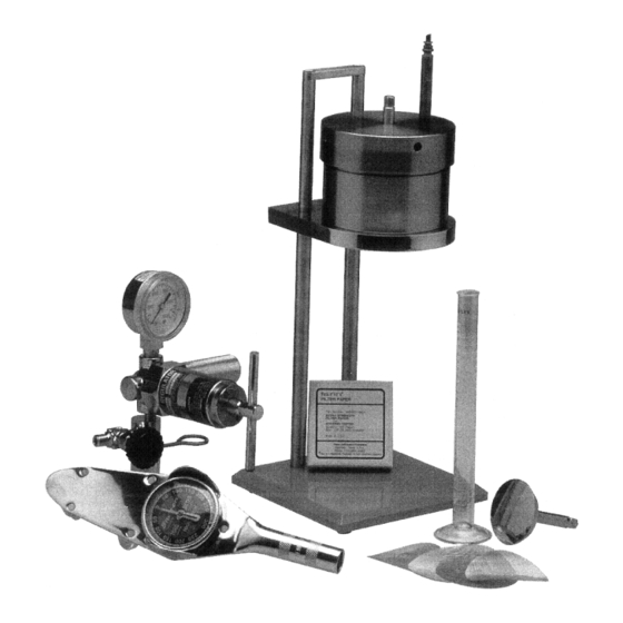
SECTION 1 GENERAL INFORMATION The Differential Sticking Tester Apparatus was designed to determine how likely a given drilling fluid will be to produce a "stuck pipe" situation and how effective a given drilling fluid treatment or application of spotting fluid in any given drilling fluid would be in reducing this tendency. -
Page 7: Safety Considerations
SECTION 2 SAFETY CONSIDERATIONS Safe operation of the Differential Sticking Tester requires that the operator understand and practice the correct assembly and operation of the equipment. Improper assembly, operation, or the use of defective parts poses the possibility of cell leakage or failure which could result in serious injury and damage. Following is a list of suggestions that should be observed to assure safe operation and maintenance of the Differential Sticking Tester. - Page 8 2. Make sure the instrument is setting flat on the bench and not close to the edge and that the groove in the lever is fit under the top leg support before pressing down and holding the lever to stick the torque plate. Refer to Fig. 4. Use caution that the lever does not slip and cause an accident.
-
Page 11: Timed Filtration Test Procedure
SECTION 3 TIMED FILTRATION STICKING TEST PROCEDURE (Numbers in [ ] refer to Fig. 1 thru 5) The general procedure for assembling and operating the instrument is basically the same whether the test described in Section 3 or Section 4 is being run. Ensure that the apparatus is clean. - Page 12 12. Close the bleed valve on the CO assembly. 13. Turn the regulator handle counterclockwise until the diaphragm pressure is relieved. 14. Insert the CO cartridge [25] into the knurled CO holder. Tighten the holder onto the head, puncturing the cartridge. 15.
- Page 15 10. Record each of these readings, then calculate the average torque reading. Record the plate sticking time. 11. Turn the regulator handle counterclockwise until the diaphragm pressure is not felt. Then open the bleed-off valve. C. Dis-assembly and Cleaning 1. Remove the empty CO cartridge (if spent.) 2.
-
Page 17: Calculations And Theory Of Measurements
SECTION 4 CALCULATIONS AND THEORY OF MEASUREMENT Stuck Tendency Coefficient Using the standard test described in Section 3 "Standard Test Procedure" and the 12.5" (31.75 cm) radius'd plate and 477.5 psi (3292 kPa), the average of 6 "break" readings taken within 30 seconds of one another divided by 1000 is known as the STUCK TENDENCY COEFFICIENT ) of a drilling fluid. - Page 18 Derivation-Bulk Sticking Coefficient The bulk sticking coefficient (K ) is the ratio of the force necessary to initiate sliding (F ) of the plate to the normal force (F ) on the plate. Let Tu = average of reading from torque wrench (inch-pounds) R = radius of plate (inches) = height above flat surface of cake around edge of plate (inches) P = cell pressure, (psi) differential (inlet to outlet)
- Page 19 Calculation for use when taking into account the edge effects is derived from the measured torque as follows: R = 1 inch and assuming that the 477.5 psi (3292 kPa) on the average is achieved only 2/3 the distance of the cake deposition up the edge: The normal force (F The differential or normal force (F ) on the plate is derived by multiplying the area by...
- Page 20 Ignoring edge effects: For a standard pressure of 477.5 psi (3292 kPa): And for R = 1 inch): Taking into account edge effects: For a standard pressure of 477.5 psi (3292 kPa) and R = 1 inch The Stuck Tendency Coefficient (K ) is: NOTE: is not valid for the flat plate because the stuck area is either 0 or...
- Page 21 Example 1. The drilling fluid sample is mixed and loaded into the cell, then pressurized at 477.5 psi (3292 kPa) for 10 minutes. The torque plate is seated using the lever and holding for two minutes. Eight minutes are allowed to pass, then breaking torque is measured in four breaks, 30 seconds apart, at 36 inch pounds (41.47 kg-cm), 39 inch pounds (44.93 kg-cm), 40 inch pounds (46.08 kg-cm), and 41 inch-pounds (47.23 kg-cm).
-
Page 23: Exploded View Pressure Regulator
Fig. 7 Exploded View Pressure Regulator... -
Page 25: Cleaning And Maintenance
SECTION 5 CLEANING AND MAINTENANCE Standard laboratory procedures apply to the cleaning of the Differential Sticking Tester. After each test, the cell should be dis-assembled completely and thoroughly cleaned and dried of all sample and other contaminants, with particular attention to "O" rings and "O" ring grooves. Wash and dry the support screen and locking mesh disc. - Page 26 Safety Considerations of Pressure Systems Safe operation of pressurized equipment requires the pressurizing system be properly maintained. Specific procedures for the safe use of pressure regulators are listed below: 1. Never subject a regulator to inlet pressure greater than its rated inlet pressure, as shown on the regulator body.
- Page 27 Some of the more common symptoms of a possibly faulty regulator are listed below: 1. Gas leaking at the regulator outlet when the adjusting screw is completely released 2. With no flow through the system (downstream valves closed and adjusting screw in), working pressure increasing steadily above set pressure.
-
Page 29: Parts List
SECTION 6 PARTS LIST (Item Numbers Refers to Fig. 8) ITEM NO. PART NO. DESCRIPTION STAGE, LEGS & BASE 209471 CO2 PRESSURIZED ASSEMBLY 205091 RETAINER WRENCH LEVER 206915 CELL BODY 206916 CELL CAP 206917 CELL SCREEN HOLDER 206918 FILTER RETAINER RING 206913 FLAT BOTTOMED TORQUE PLATE 206908... - Page 30 Warranty and Returns Warranty Fann Instrument Company warrants its products to be free from defects in material and workmanship for a period of 12 months from the time of shipment. If repair or adjustment is necessary, and has not been the result of abuse or misuse within the 12- month period, please return, freight prepaid, and correction of the defect will be made without charge.
Need help?
Do you have a question about the 21150 and is the answer not in the manual?
Questions and answers