Advertisement
Available languages
Available languages
Quick Links
SPECIFICATIONS
Output Rating.................................5 Amps 28VAC or DC Max.
Power .........................................................18V to 35V, @ 30ma
RF Frequency ................................................................390MHz
If the power is other than shown in specifications,
Accessory Transformer Model 95 is required. Model 86
Coaxial Cable Kit is also available.
Accessory Transmitters — Series 50, 60 and 80.
WAR N ING
Children operating or playing with a garage door opener can
injure themselves and others. The garage door could close
and cause serious injury or death. Do not allow children to
operate the door control push button or the remote control
transmitters.
Install receiver (and all door control push buttons) out of the
reach of children and away from all moving parts of the door and
door hardware, but where the garage door is visible.
This radio receiver incorporates constant closure contacts,
and thus use on residential operators incorporating fail-safe
infra-red sensors is prohibited
Disconnect power to opener(s) before installing receiver.
Garage door opener #1 (without transformer)
Refer to Figure 1 for wiring connections:
Connect 2-conductor bell wire (not supplied) to receiver terminal
screws 3 and 4, and to the opener terminal screws used for the
wall push button.
Also, connect bell wire to receiver terminal 2 and opener terminal
screw 3; use a jumper wire to connect receiver terminals 1 and 3.
Garage door opener #1 (with transformer 95)
Refer to Figure 2 for wiring connections:
Connect bell wire to receiver terminal screws 1 and 2, and to
transformer terminals. Also, connect bell wire (not supplied) to
receiver terminal screws 3 and 4, and to opener terminal screws
used for wall push button.
Garage door opener #2: Connect white and white/red bell wire
from the receiver to the opener terminal screws used for the wall
button.
Use a screwdriver to pry open the receiver cover, Figure 3.
Re-connect power to the opener and the accessory
transformer, if used.
• Follow code switch remote control instructions, if applicable .
• Select a remote push button to operate opener #1.
• Press and hold the selected remote button. Then press and
release the "smart" button labeled "A" on the receiver. The
adjacent indicator light will FLASH.
•. Release the remote push button. Opener #1 will now operate
when the selected remote control push button is pressed.
Repeat the procedure, using "smart" button "B", with the other
remote push button to program the second opener
Note: If a remote control push button is not pressed within
30 seconds, indicator light adjacent to selected "smart"
button will turn OFF. In that case, repeat the programming.
FOR SERVICE DIAL OUR TOLL-FREE NUMBER:
1-800-528-2806
114A1790D
LiftMaster 2-Channel Universal Receiver
To comply with FCC/IC rules, adjustment or modification of receiver and/or
transmitter is prohibited, except for changing the code setting or replacing the
battery. THERE ARE NO OTHE
Universal receiver Model 422LM can be used to operate
two residential garage door openers or entryways with
Model Series 60 code switch remote controls having red
indicator lights, and up to four Model Series 80 "Smart"
remote controls with green indicator lights.
I n general, code switch remote controls are used when
several persons are operating the same device. The code
switches must be set to matching positions in all remote
controls used to operate the same receiver . (Refer to the
instructions included with Series 60 and 80 remote controls).
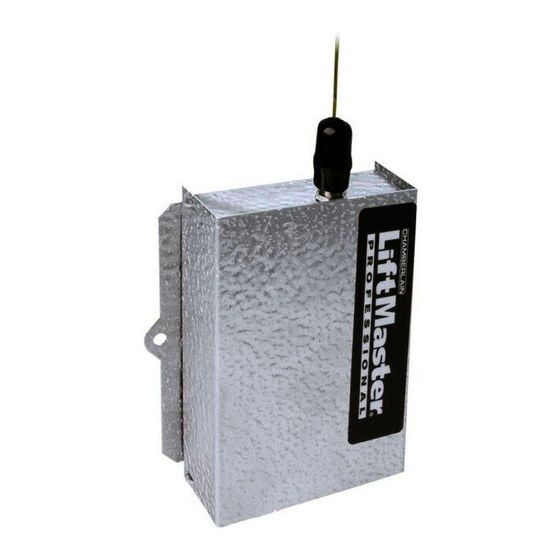
Both the receiver and the antenna use TV Type F coaxial
connectors. The antenna can be plugged directly onto the
receiver or mounted to a bracket and connected to the receiver
with Model 86 Coaxial Cable Kit, if you need more range.
Select a location for the receiver which allows access to the
terminals and space for the antenna (as far from metal
structures as possible and preferably with the antenna in an
upright position). Fasten the receiver securely with screws
through the two holes provided in the cover flanges.
Figure 1
Figure 2
RECEIVER
RED
Indicator
Light
GREEN
Indicator
Light
© 2000, The Chamberlain Group, Inc.
All Rights Reserved
OWNER'S MANUAL
R USER SERVICEABLE PARTS.
Receiver
Wall
(Bottom)
Button
1
Operator
1
Common
2
2
3
Relay
3
4
24 v
Transformer 95
Receiver
Wall
(Bottom)
Button
Operator
1
1
Common
2
2
Relay
3
3
24 v
4
Select a
Push Button
Push
Button
Model 422LM
Trans
Primary
Trans
Primary
Figure 3
Smart
Button
"B"
Smart
Button
"A"
Printed in Mexico
Advertisement

Subscribe to Our Youtube Channel
Related Manuals for Chamberlain LiftMaster 422LM


Summary of Contents for Chamberlain LiftMaster 422LM
- Page 1 30 seconds, indicator light adjacent to selected "smart" Light button will turn OFF. In that case, repeat the programming. FOR SERVICE DIAL OUR TOLL-FREE NUMBER: Push 1-800-528-2806 Button © 2000, The Chamberlain Group, Inc. 114A1790D All Rights Reserved Printed in Mexico...
- Page 2 30 secondes, la lampe témoin adjacente au bouton "Smart" choisi s’éteindra. Si c’est le cas, répéter la Bouton- programmation. poussoir POUR LE SERVICE PRIÈRE DE COMPOSER NOTRE NUMÉRO SANS FRAIS: 1-800-654-4736 © 2000, The Chamberlain Group, Inc. 114A1790D Touts Droits Réservés Imprimé au Mexique...
Need help?
Do you have a question about the LiftMaster 422LM and is the answer not in the manual?
Questions and answers