Advertisement
Available languages
Available languages
Installation
1
Before you begin
Your garage door opener has an internal gateway located on the receiver logic board. After installing the new receiver logic board, use the MyQ
garage door opener to your MyQ
®
account. The products illustrated in the instructions are for reference. Your product may look different.
To prevent possible SERIOUS INJURY or
DEATH:
• Disconnect ALL electric and battery
power BEFORE performing ANY service
or maintenance.
To prevent damage to the receiver/logic
board, DO NOT touch printed circuit board
of replacement receiver/logic board during
installation.
ALWAYS wear protective gloves and eye
protection when changing the battery or
working around the battery compartment.
2
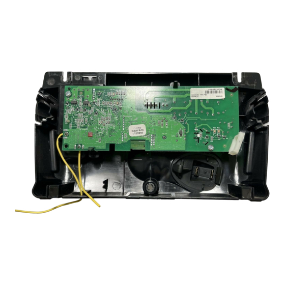
Remove the receiver logic board
2.1 Disconnect the wires from the quick-connect terminals (A).
Remove the receiver logic board end panel from the garage
door opener.
A
To insert or remove
the wires from the
terminal, push in the
tab with a
screwdriver tip.
1.1 Remove the light lens by pulling the
top sides of the light lens and rotate the
light lens down. Squeeze the light lens
clips to remove lens from end panel.
WARNING: This product can expose you to chemicals including lead, which are known to the State of California to cause cancer or birth
defects or other reproductive harm. For more information go to www.P65Warnings.ca.gov
2.2 Unplug the wire harnesses from the receiver logic
board. You may need needle-nosed pliers to remove
the harnesses.
RECEIVER LOGIC BOARD REPLACEMENT
1.2 To maintain your warranty, place the
provided label over the existing label
on the end panel of the garage door
opener.
TO ERASE ALL
RECEIVER CODES
1. Press and HOLD
receiver orange
ERASE button
6 seconds. Indicator
light will turn ON.
2. Release button
when light turns OFF.
PART NO.:
NO. DE PIEZA:
DATE:
CANADA:
THE CHAMBERLAIN
GROUP, INC., USA
Ensamblado en México
TO ERASE ALL
RECEIVER CODES
TODOS LOS CÓDIGOS DEL
ELIMINACIÓN DE
1. Press and HOLD
RECEPTOR
ERASE button
receiver orange
1. MANTENGA PRESIONADO
Assembled in Mexico
6 seconds. Indicator
del receptor durante 6
el botón naranja "ERASE"
light will turn ON.
segundos. La luz del
indicador se encenderá.
2. Release button
when light turns OFF.
2. Suelte el botón cuando la
luz se apague.
132C2280-3D
PART NO.:
NO. DE PIEZA:
CANADA:
DATE:
DANGER
PELIGRO
THE CHAMBERLAIN
GROUP, INC., USA
Ensamblado en México
Assembled in Mexico
132C2280-3D
2.3 Remove the receiver
logic board from the
end panel by removing
the 2 screws and
releasing the 2 clips.
1
Model 050ACTWF
®
serial number found on the provided label to add your
1.3 Disconnect power to the garage door
opener.
ELIMINACIÓN DE
TODOS LOS CÓDIGOS DEL
RECEPTOR
1. MANTENGA PRESIONADO
el botón naranja "ERASE"
del receptor durante 6
segundos. La luz del
indicador se encenderá.
2. Suelte el botón cuando la
luz se apague.
DANGER
PELIGRO
Wire clip
Clips
Screws
Advertisement
Table of Contents

Related Manuals for Chamberlain 050ACTWF


Summary of Contents for Chamberlain 050ACTWF
- Page 1 RECEIVER LOGIC BOARD REPLACEMENT Model 050ACTWF Installation Before you begin Your garage door opener has an internal gateway located on the receiver logic board. After installing the new receiver logic board, use the MyQ ® serial number found on the provided label to add your garage door opener to your MyQ ®...
- Page 2 Install new receiver logic board 3.2 Insert the antenna wires through 3.1 Connect the wire harnesses to the 3.3 Reinsert the wires. 3.4 Install the light lens by aligning with the holes in the end panel. Snap the new receiver logic board. When Door control wires: the hinges and snapping into place.
-
Page 3: Program The Travel
Adjustment Program the travel 1.1 Press and hold the Adjustment Button 1.2 Press and hold the UP Button until the 1.3 Once the door is in the desired until the UP Button begins to fl ash and/ door is in the desired UP position. UP position press and release the Without a properly installed safety reversal or a beep is heard. -
Page 4: Test The Safety Reversal System
Test the Safety Reversal System If the door stops and does not reverse on the 2.1 With the door fully open, place a 2.2 Press the remote control push button obstruction, increase the down travel (refer to 1-1/2 inch (3.8 cm) board (or a 2x4 laid to close the door. -
Page 5: Installation
REMPLACEMENT DE LA CARTE LOGIQUE DU RÉCEPTEUR Modèle 050ACTWF Installation Avant de commencer Votre ouvre-porte de garage a un portail interne localise sur la plaque de logique de réception. Après avoir installé la nouvelle plaque de logique de réception, utilisez le numéro de série de MyQ ®... - Page 6 Installez le nouvelle carte logique du récepteur 3.2 Insérez les fi ls d’antenne à travers 3.3 Réinsérez les fi ls. 3.4 Installez la lentille en l’alignant avec 3.1 Connectez les harnais de fi ls à la les trous du panneau d’extrémité. Fils de commande de la porte : les charnières et en l’enclenchant en nouvelle carte logique du récepteur.
- Page 7 Réglages Programmation de la course 1.1 Appuyer sur le bouton de réglage 1.2 Appuyer sur le bouton UP et le 1.3 Une fois que la porte est dans la et le maintenir enfoncé jusqu’à maintenir enfoncé jusqu’à ce position d’ouverture désirée, appuyer ce que le bouton UP commence que la porte soit à...
- Page 8 Essai du système d’inversion de sécurité Si la porte s’arrête et ne remonte pas en 2.1 La porte étant entièrement ouverte, 2.2 Appuyer sur le bouton-poussoir de la raison de l’obstruction, augmenter la course placer une planche de 3,8 cm (1 1/2 télécommande pour fermer la porte.
-
Page 9: Antes De Comenzar
REEMPLAZO DE LA TARJETA LÓGICA DEL RECEPTOR Modelo 050ACTWF Installation Antes de comenzar ® Su abre-puertas de garaje tiene una gateway interno que se encuentra en la tabla lógica. Después de instalar la nueva tabla lógica, utilice el número de serie de la MyQ se encuentra en la etiqueta, ®... - Page 10 Instale la nueva tarjeta lógica del receptor 3.1 Conecte el hato de cables a la nueva 3.2 Inserte los cables de la antena a través 3.3 Vuelva a insertar los cables. 3.4 Instale la lente de luz alineándola con tarjeta lógica del receptor. Al volver de los orifi...
- Page 11 Ajustes Programación de la carrera 1.1 Oprima y mantenga oprimido el 1.2 Oprima y mantenga oprimido 1.3 Una vez que la puerta esté en la botón “Ajuste” hasta que el botón el botón ARRIBA hasta que la posición deseada, oprima y suelte el ARRIBA empiece a parpadear y/o puerta se encuentre en la posición Si el sistema de retroceso de seguridad no se ha...
- Page 12 Para sincronizar el control fi jo con el abre-puerta pulsar el control hasta que se active el abre-puerta (podría llevar hasta tres intentos). Prueba el control de la puerta a pulsar el pulsadora de barra, cada vez que se pulsa el control fi jo se activará el mecanismo del abre-puerta. © 2015, The Chamberlain Group, Inc. All Rights Reserved Tous droits réservés...
Need help?
Do you have a question about the 050ACTWF and is the answer not in the manual?
Questions and answers