Advertisement
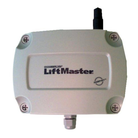
Wiegand Receiver with Passport Technology
Installation and Operation Instructions
SPECIFICATIONS
Power: 12VDC, 50 mA
Temperature Rating: -40º to +185º F
RF Frequency: 390 MHZ
Accessory Transmitters
Visors:
CPT1, CPT2, CPT3, CPT4
Keychains: CPTK1, CPTK3, CPTK1PH, CPTK3PH
TABLE OF CONTENTS
SETTING THE SWITCHES .................................................... 2
INSTALLATION AND WIRING ............................................... 4
TESTING AND TROUBLESHOOTING .................................. 5
APPENDIX: FACILITY CODE SWITCH SETTINGS .............. 6
OVERVIEW
The Wiegand Receiver (CPWR) is a communication
device that transmits an information packet to an access
control unit such as a Sentex Telephone Entry System.
All receiver units utilize the latest in Chamberlain® rolling
code technology.
ACCESS CONTROL COMPATIBILITY
The CPWR outputs a 26-bit or 30-bit Wiegand format
compatible with Sentex access control systems.
Children operating or playing with a garage
door/gate opener can injure themselves
and others. The door/gate could close and
cause serious injury or death. Do not allow
children to operate the door control push
button or the remote control transmitters.
Install the receiver (and all control push
buttons) out of the reach of children and
away from all moving parts of the door/gate
hardware, but where the door/gate is
visible.
Doc 6001535, Rev G
Page 1 of 6
WARNING
Advertisement
Table of Contents

Related Manuals for Chamberlain LiftMaster CPT1


Summary of Contents for Chamberlain LiftMaster CPT1
- Page 1 WARNING control unit such as a Sentex Telephone Entry System. All receiver units utilize the latest in Chamberlain® rolling code technology. Children operating or playing with a garage door/gate opener can injure themselves and others.
-
Page 2: Setting The Switches
Setting the Switches Before making changes to any of the DIP switches, power MUST be disconnected from the receiver (unplug the terminal block from J2 on the circuit board). Otherwise, your changes will not take effect. Also, when setting the receiver’s DIP switches, refer only to the numbers silk screened on the PC board (not the numbers on the DIP switch itself). - Page 3 STEP 4: SET THE TRANSMITTER BUTTON RESPONSE(S) There are three DIP switches used to set the CPT4 transmitter button response(s). See Figure 4 Transmitter FORMAT or Figure 5. To disallow receiver response to transmitter buttons, move the DIP switch(es) to the LEFT. All button switches are factory set to ON.
-
Page 4: Installation And Wiring
Installation and Wiring PARTS SUPPLIED PARTS NOT SUPPLIED Wiegand Receiver # 6 Mounting Hardware Antenna 5-conductor shielded cable; 22 AWG wire Installation and Operation Instructions Extension Kit (Optional) STEP 1: MOUNT THE RECEIVER Mount receiver to surface using #6 hardware (not supplied). -
Page 5: Testing And Troubleshooting
RF energy. It is normal for this LED to flicker continuously while the receiver is powered DATA – Yellow This LED indicates that the receiver recognizes the transmission data as coming from a Chamberlain® transmitter with Passport technology. 1535F6 VALID – Green... -
Page 6: Appendix: Facility Code Switch Settings
Appendix: Facility Code Switch Settings Refer to Figure 1 on page 2 for the facility code DIP switch location. Also, when setting the receiver’s DIP switches, refer only to the numbers silk screened on the PC board (not the numbers on the DIP switch itself).
Need help?
Do you have a question about the LiftMaster CPT1 and is the answer not in the manual?
Questions and answers