
Related Manuals for Lennox EIM


Summary of Contents for Lennox EIM
- Page 1 Equipment Interface Module (EIM) Installation and Setup Guide 507240-03 6/2021 Supersedes 3/2020...
-
Page 2: Table Of Contents
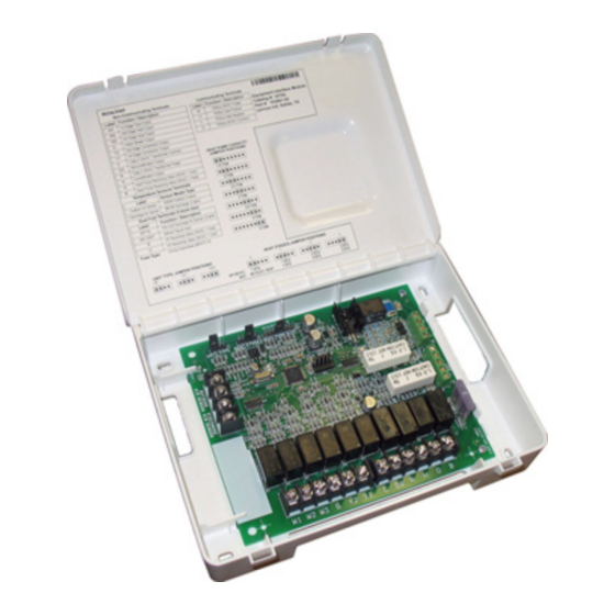
Equipment Alert Codes and Troubleshooting ...........16 The Equipment Interface Module (EIM) is used with an Lennox communicating thermostat using the R, i+, i-, and C terminals. The EIM is the interface between non-communicating HVAC equipment and Lennox communicating HVAC equipment. - Page 3 HEAT STAGES HEAT PUMP CAPACITY JUMPER TERMIINALS UNIT TYPE JUMPER JUMPER TERMINALS STATUS LED TERMINALS COMMUNICATION INDICATOR OUTDOOR AIR SENSOR CONNECTIONS ® ICOMFORT CONNECTIONS DISCHARGE AIR SENSOR CONNECTIONS DUAL-FUEL CONNECTIONS 3 AMP FUSE NON-COMMUNICATING TERMINALS Figure 1. Terminals and LEDs CAUTION Electrostatic discharge can affect electronic components.
-
Page 4: Installation
1. Set the EIM Unit Type Jumper to IFC. Installation 2. Set the EIM Heat Stage Jumper (see “Table 3. Heat Stage Jumpers” on page 5) to the applicable number of furnace heat stages or number of electric heat stages. -
Page 5: Unit Type Jumpers
Table 2. Unit Type Jumpers Positions 100% 100% Heat Jumper Indoor Unit Outdoor Unit 100% 100% 100% Position 50%, 70%. 70%. Lennox Communicating Conventional Heat Pump (default) 100% 100% 100% Furnace 33.5%, Conventional Furnace 70%, 70%. Conventional Heat Pump or air 66.5%, 100%... -
Page 6: Air Temperature Sensor Connections
Outdoor Air accessories (such as humidifiers, UV lights, etc.) terminals) NOTE: Wiring distance between the EIM and the outdoor temperature Sensor will not interfere with its accuracy. Wiring distance sensor can not exceed 150 feet (45 meters) when wired with... -
Page 7: Led Indicators
RSBus. 2. Cycle power to the control that is displaying the soft disable code. 3. Touch the Lennox icon on the thermostat home screen and hold until the installer warning screen appears. 4. Touch yes to continue. -
Page 8: Icomfort S30 Commissioning (Conventional Outdoor Unit)
6” (152mm) If any jumpers were set incorrectly AFTER commissioning was completed, then reposition jumpers to correct positions. Re-running the commissioning procedure will be required at the Lennox communicating thermostat. This completes the configuring of the conventional outdoor unit. iComfort S30 Commissioning (Conventional Outdoor Unit) 8”... -
Page 9: Duel-Fuel Operations
Duel-Fuel Operations To use the EIM in dual-fuel mode, the following equipment combinations Lennox Lennox Equipment Interface and configuration is required. Communicating Communicating Model (EIM) Thermostat Furnance Defrost Air Tempering Kit (67M41) will be required. The included DT1 discharge temperature probe is inserted in the furnace air outlet between... -
Page 10: Field Wiring
Field Wiring Table 9. Wiring Diagrams EIM Jumper Settings System Type Indoor Unit Outdoor Unit Diagrams Unit Type Number and Type of Heat Stages Air Conditioner Conventional Furnace Conventional Air Conditioner Set to number of furnace stages. Figure 9 on page 11... - Page 11 Y2 OUT Y2 OUT IS FOR TWO-STAGE UNITS ONLY (XP16 & XP19) Figure 11. Dual-Fuel - Lennox Communicating Furnace with Conventional Heat Pump (1 or 2-Stage) Figure 9. Conventional Furnace or Air Hander with Conventional Air Conditioner (1 or 2-Stage)
- Page 12 Y2 OUT Figure 13. Dual-Fuel - Conventional Furnace with Conventional Heat Pump (1 or 2-Stage) ICOMFORT SERIES THERMOSTAT Y2 OUT Figure 14. Baseboard Heat - Conventional Air Handler (CBX32MV(-6) or CBX40UHV) with either a Lennox Communicating Air Conditioner or Heat Pump...
- Page 13 Y2 OUT Figure 16. Dual-Fuel - Lennox Communicating Furnace, iHarmony Zoning and Conventional Heat Pump...
- Page 14 ICOMFORT SERIES THERMOSTAT ICOMFORT SERIES THERMOSTAT REMOVE JUMPER BETWEEN R AND W2 IF PRESENT. IT MAY CAUSE ERRONEOUS ALERT CODE 125. Y2 OUT REMOVE JUMPER BETWEEN R AND W2 IF PRESENT. IT MAY CAUSE ERRONEOUS ALERT Y2 OUT CODE 125. Figure 18.
- Page 15 Service Soon alerts will escalate to Service Urgent. • Service Soon alerts are found only in under the installer alert button. • Information Only-Dealer is information only and helps Lennox interpret test results and understand complicated behaviors. Information Only are not reported to homeowner or dealer.
-
Page 16: Alert Codes And Troubleshooting
> Notifications Thermostat did not find an indoor unit. Make sure there is an Lennox communicating indoor unit on the system. Check for voltage and missing component. Check R, i+, i- and C connections at mag-mount or subbase, smart hub and all attached communicating components. - Page 17 Review both active and cleared alerts. Wi-Fi – Press and hold the Lennox logo on the bottom right of stat for 5 seconds to access the dealer control center. Follow the prompts to access the dealer / installer screen and select the “Alerts” tab. Review alert code details to determine which device or unit has the communication problem.
- Page 18 Table 1. Alert Codes and Troubleshooting GF= Gas Furnace, AH=Air Handler, ID=Indoor unit (GF or AH), HP=Heat Pump, AC=Air Conditioner, OD=Outdoor Unit (AC or HP), PA=Pure Air S, ZA=Zone system and TS=Thermostat Actual Displayed Alert Text Alert Priority How to clear Under dealer Component or System Operational State and Troubleshooting Tip Code...
- Page 19 Table 1. Alert Codes and Troubleshooting GF= Gas Furnace, AH=Air Handler, ID=Indoor unit (GF or AH), HP=Heat Pump, AC=Air Conditioner, OD=Outdoor Unit (AC or HP), PA=Pure Air S, ZA=Zone system and TS=Thermostat Actual Displayed Alert Text Alert Priority How to clear Under dealer Component or System Operational State and Troubleshooting Tip Code...
- Page 20 If detected (reading in range), appropriate feature will be set as ‘installed’ and shown in the ‘About’ screen. There is a discharge air temperature sensor issue. Confirm there is no short or open circuits in the Lennox communicating thermostat connections to any of the other components in the communication system.
- Page 21 If error is applicable to the XC20, XC25, XP20 or XP25, the outdoor control will need to be replaced. Lennox communicating thermostat sends a Y1 compressor demand to the indoor control requesting it to relay the demand to the outdoor unit.
- Page 22 Lockout If 24VAC is present, replace the outdoor control. The heat pump defrost cycle has taken more than 20 minutes to complete. Defrost cycle lasts longer than 20 minutes. AH EIM Defrost Automatically clears when Service Soon Out Of Cycle W1 signal is removed.
Need help?
Do you have a question about the EIM and is the answer not in the manual?
Questions and answers