Advertisement
Quick Links
©2018 Lennox Industries Inc.
Dallas, Texas, USA
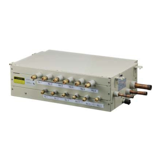
V8MSBB04 Shown
THIS MANUAL MUST BE LEFT WITH THE
OWNER FOR FUTURE REFERENCE
These instructions are intended as a general guide and do
not supersede local codes in any way. Consult authorities
having jurisdiction before installation.
WARNING
Improper installation, adjustment, alteration, ser-
vice or maintenance can cause property damage,
personal injury or loss of life.
Installation and service must be performed by a li-
censed professional HVAC installer, service agency
or the gas supplier.
Failure to follow safety warnings and these instruc-
tions exactly could result in property damage, dan-
gerous operation, serious injury, or death.
Any additions, changes, or conversions required in
order for the appliance to satisfactorily meet the ap-
plication needs must be made by a licensed profes-
sional HVAC installer (or equivalent) using factory-
specifi ed parts.
Do not use this system if any part has been under
water. A fl ood-damaged appliance is extremely dan-
gerous. Immediately call a licensed professional
HVAC service technician (or equivalent) to inspect
the system and to replace all controls and electrical
parts that have been wet, or to replace the system, if
deemed necessary.
WARNING
The Mode Selection Box is factory fi tted with Black
plastic caps over the fl are connection points. These
must be replaced with the supplied brass fl are nuts.
Under no circumstances can the plastic caps be used
as a permanent seal even when not all ports are used.
A suitable blanking device must be fi tted on all unused
ports.
INSTALLATION
INSTRUCTIONS
Mode Selection Box
VRF SYSTEMS
507453-05
05/2018
Shipping and Packing List
Check the components for shipping damage. If you fi nd
any damage, immediately contact the last carrier.
Package 1 of 1 contains the following:
1 - Assembled mode selection box
3 - Insulation sleeves for piping from outdoor unit
1 - 1" X ¾" condensate drain adaptor
1 to 6* - ⅜" to ¼" adaptors
1 to 6* - ⅝" to ½" adaptors
1 to 6* - ¼" brass fl are nuts
1 to 6* - ½" brass fl are nuts
1 to 6* - Gas pipe insulation sleeve(s)
1 to 6* - Liquid pipe insulation sleeves
*Quantity of these items depends on number of refrigerant
piping connection pairs.
Installation
Mode selection boxes V8MSBB01, V8MSBB02, V8MS-
BB03 and V8MSBB04 are used with VRA heat recovery
outdoor units to allow simultaneous heating and cooling in
multiple zones. Mode selection boxes are designed for in-
door installation only.
Mode selection boxes include solenoid valves which control
refrigerant fl ow through the individual indoor units so that
unit operation (heating or cooling) matches the comfort re-
quirements being sent by the occupant.
Mode selection boxes are sized to accommodate up to 24
indoor units. See Table 1.
Mode selection boxes are equipped with fl ared fi ttings for
indoor unit refrigerant piping connections and braze fi ttings
for outdoor unit connections.
Refer to the Product Specifi cation bulletin (EHB) for the
proper use of mode selection boxes with matching VRA
heat recovery units, indoor units, branch pipes, line sets
and controls.
CAUTION
As with any mechanical equipment, contact with sharp
sheet metal edges can result in personal injury. Take
care while handling this equipment and wear gloves and
protective clothing.
1
Advertisement

Related Manuals for Lennox V8MSBB01


Summary of Contents for Lennox V8MSBB01
- Page 1 Installation censed professional HVAC installer, service agency or the gas supplier. Mode selection boxes V8MSBB01, V8MSBB02, V8MS- Failure to follow safety warnings and these instruc- BB03 and V8MSBB04 are used with VRA heat recovery tions exactly could result in property damage, dan- outdoor units to allow simultaneous heating and cooling in gerous operation, serious injury, or death.
- Page 2 Approved methods of recovery, recycling or reclaiming these proposed changes. must be followed. Fines and/or incarceration may be Upon receipt of this new information the Lennox VRF levied for non-compliance. applications department will confi rm any changes that may be applicable to this installation. If changes are required, a new piping diagram will be produced and will supersede all other previously provided documents.
-
Page 3: Unit Dimensions - Inches (Mm)
Unit Dimensions - inches (mm) V8MSBB01, V8MSBB02, V8MSBB03, V8MSBB04 (229) CONDENSATE MOUNTING DRAIN 1 (25) dia. LUGS (4) PRESSURE GAS PIPE TO OUTDOOR UNIT 11-3/4 HIGH (298) PRESSURE 23-5/8 GAS PIPE (600) TO OUTDOOR UNIT LIQUID PIPE TO OUTDOOR CONNECTIONS TO INDOOR UNITS... -
Page 4: Concrete Ceiling
Installation Clearances - inches (mm) CONCRETE CEILING 11-7/8 (300) Minimum PIPE REFRIGERANT HANGER PIPE 59 (1500) 59 (1500) 2 (51) Maximum Maximum Minimum SUSPENDED CEILING Required! Suitably sized access panel required to provide full access to electrical panel (610) 15-3/4 (914) (400) Minimum... - Page 5 • The mode selection box must be sloped 1/8” toward Figure 1. Suspending Methods condensate drain outlet. NOTE - Threaded rod (requirement of Lennox • Provide suffi cient clearance around mode selection warranty program) is the ONLY acceptable method of box to allow 3 feet of straight pipe before the fi...
- Page 6 WARNING Refrigerant Piping Connections The Mode Selection Box is factory fi tted with Black WARNING plastic caps over the fl are connection points. These Refrigerant leaks are unlikely; however, if a refrigerant must be replaced with the supplied brass fl are nuts. leak occurs, open a door or windows to dilute the Under no circumstances can the plastic caps be used refrigerant in the room.
- Page 7 Adaptors are provided with the mode selection piping schematic in Figure 9. box to accommodate the use of different pipe sizes. Refer to the LVSS (Lennox VRF Selection Software) • Allow a minimum of 3 feet between the mode selection piping report for pipe sizes.
- Page 8 DO NOT over-tighten 36000 fl are nuts. 48000 Torque Always refer to the provided piping diagram for correct pip- ing sizes. Contact Lennox VRF Application support for as- Wrench sistance with piping sizing or an updated piping diagram. Backup Mode Wrench Selection NOTE - 5/8”...
- Page 9 It is imperative that the system piping is installed per the pipe sizes. LVSS (Lennox VRF Selection Software) piping report! If NOTE - All VVCA units have brazed connections. Piping the measurements on the Lennox VRF piping diagram do not match the anticipated fi...
- Page 10 IMPORTANT Locate fi rst branch pipe kit of system centrally to ensure even distribution of refrigerant. Figure 8. Mode Selection Box Branch Pipe Kits...
- Page 11 (96) (120) (120) NOTE - Indoor and outdoor unit (024) capacities are shown in parenthesis (024) (009) (048) LEGEND Branch Pipe (048) (024) Mode Selection Box (MS) Indoor Unit (024) (018) (018) (018) (048) (048) (009) PIPE AND COMPONENT NAMES Name Designation Outdoor Unit Connection Pipe...
- Page 12 Branch Pipe Kit Placement Provide 24 inches to 36 inches of straight pipe before CAUTION and after each branch pipe kit to avoid creating refrig- 24 inches minimum straight pipe required before and after erant turbulence and fl ash points. Failure to follow 24 branch pipe kit to prevent capacity loss and equipment inch minimum guideline can lead to reduced capacity damage.
- Page 13 Condensate Drain Connection A 1 inch OD condensate drain connection is provided The mode selection box must be sloped 1/8” toward drain on the mode selection box. Route condensate piping to outlet. a suitable drain per best practices, taking care to slope the drain properly to ensure drainage.
- Page 14 Power Distribu on Box L1/L2/L3 L1/L2/L3 L1/L2/L3 L1/L2 L1/L2 L1/L2 L1/L2 L1/L2 L1/L2 L1/L2 L1/L2 L1/L2 L1/L2 L1/L2 L1/L2 Legend PQE Communica on wiring L1/L2 Single-Phase power wiring L1/L2/L3 Three-Phase power wiring Electrical disconnect switch Figure 11. Typical Power Wiring Diagram (VRF Heat Recovery System Shown)
- Page 15 NOTE - Each communication wire from the mode selection box should follow the refrigerant piping for that port. Figure 12. Typical Communication Wiring Diagram (VRF Heat Recovery System)
- Page 16 208-230V NOTE - Indoor c ommunications cable To other MS boxes on must match indoor piping connections. same refrigeration circuit. Figure 13. V8MSBB01 Connections VHIA072 and VHIA096 Only 2# MS UNIT (P Q E) OUTDOOR UNIT 1# MS UNIT TRANS...
-
Page 17: Wiring Connections
Wiring Connections TRANS1 EXVA TRANS2 M-I(5, 6) M-I(1~4) BLUE T4C T4C1 P Q E P Q E P Q E P Q E P Q E P Q E P Q E L1 L2 POWER IN TO OUTDOOR TO INDOOR 4 TO INDOOR 6 TO INDOOR 5 TO INDOOR 3... - Page 18 Figure 16. Piping for VHIA072 or 096 when V8MSBB01 is Greater Than 15 ft. (4.5 m) Away - VRA Heat Recovery V8MBB01 VHIA072/096 5/8” 3/8” Figure 17. Piping for VHIA072 or 096 when V8MSBB01 is Equal To or Less Than 15 ft. (4.5 m) Away - VRA Heat Recovery...
- Page 19 Incoming liquid line connection Connect these two pipes as Incoming shown in “A” suction line below. connection Incoming suction line connection Incoming liquid line connection Connect these two pipes as shown in “A” left. Figure 18. VHIA072 and 096 Refrigerant Connections System Communication Wiring •...
- Page 20 Troubleshooting LED Lamp Defi nitions LED Lamp Normally ON Slow Flash Flash LED 1 Outdoor unit ON Outdoor unit standby Outdoor unit communication error LED 2 Indoor unit ON of this MS Indoor unit OFF this MS Indoor unit communication error Operation Mode References FORCED COOLING MODE MAIN COOLING MODE...
-
Page 21: Spot Check
Spot Check Notes Description Indoor unit quantity under the port Operation mode under the port When actual temp. ≤-9°, show -9; When in- Subcool inlet temperature door unit is OFF or operating Fan mode, show -9 (means invalid value) Superheated outlet temperature T2 average of the system if operation mode is heating under the port. - Page 22 Technical Support 1-844-GET-VRF1 (1-844-438-8731) vrftechsupport@lennoxind.com www.LennoxVRF.com Download the app from the Apple App Store or the Google Play store.
Need help?
Do you have a question about the V8MSBB01 and is the answer not in the manual?
Questions and answers