
Related Manuals for Joy-it DSO138-MINI


Summary of Contents for Joy-it DSO138-MINI
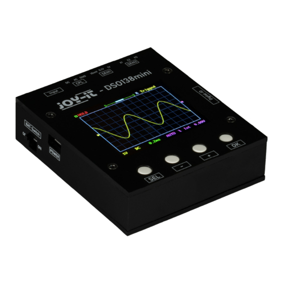
- Page 1 DSO138-MINI Mini digital oscilloscope Joy-IT powered by SIMAC Electronics GmbH - Pascalstr. 8 - D-47506 Neukirchen-Vluyn - www.joy-it.net...
-
Page 2: Table Of Contents
TABLE OF CONTENTS 1. General Information 2. Overview 3. Setup 4. Configuration 5. Opening the device 6. Connecting an external battery unit 7. Trimmer calibration 8. External trigger connection, reset & other connections 9. Additional functions 10. Safety instructions 11. Other Information 12. -
Page 3: General Information
If you encounter any unexpected problems, please feel free to contact us. The new Joy-IT oscilloscope set DSO-138-Mini is the improved successor of the DSO-138, which is the ideal complement to the multimeter and can also be used mobile with the help of an optionally available battery. -
Page 4: Setup
First, connect a microUSB cable to the power supply input as shown in the following picture. The DSO138-Mini requires approx. 120 mA at a voltage of 5 V. Make sure that your power supply is rated for this. Now also connect the lead to the signal input of your device. -
Page 5: Configuration
4. CONFIGURATION As soon as the device is supplied with voltage, it starts up automatically. The sensitivity and the coupling can be adjusted via the switches next to the signal input: CPL: INPUT COUPLING Here the coupling mode can be set to DC, AC or ground. With DC coupling, all components of the input signal are displayed. - Page 6 All other configuration options can be set using the buttons below the display: THE FOLLOWING CONFIGURATIONS CAN BE MADE: DISPLAY MODE The active mode can be set between Running and Hold. Running describes the normal measuring mode. Hold pauses the current measurement at the current time.
-
Page 7: Opening The Device
5. OPENING THE DEVICE Under certain circumstances it may be necessary to open the device, for example to connect an external battery, to adjust the trimmers or to expose the other, optional connections. To do this, first, open the housing by removing the screws on the back of the device: Now remove the cover from the housing and pull the motherboard off the device so that only the display unit remains in the housing. - Page 8 If necessary, the display can additionally be removed by removing the screws on the front of the device. Afterwards, the display can be removed from the front of the case.
-
Page 9: Connecting An External Battery Unit
6. CONNECTING AN EXTERNAL BATTERY UNIT The DSO138-Mini can also be powered by a 3.7 V lithium-ion battery as an alternative to the power supply via the micro USB connector. Attention! An external battery unit must either be charged externally or a JYE118 module must also be installed. -
Page 10: Trimmer Calibration
7. TRIMMER CALIBRATION If necessary, the capacitor trimmers can be adjusted to calibrate the instrument. To do this, first, open the device as described in Chapter 5 - Opening the device. After you have removed both the mainboard and the display from the housing, you can first place the display unit back on the mainboard. - Page 11 Now adjust the trimmer capacitor C4 with a screwdriver so that an even, rectangular waveform is created. Now set the switch [SEN1] to 1 V and the switch [SEN2] to X1. Now repeat the setting procedure with capacitor C6. You can use the following illustrations as a guide for calibrating the trimmer capacitors: Not set properly Not set properly...
-
Page 12: External Trigger Connection, Reset & Other Connections
8. EXTERNAL TRIGGER CONNECTION, RESET & OTHER CONNECTIONS Alternatively, an external trigger signal can also be connected to the device. To do this, first, open the device as described in Chapter 5 - Opening the device. After you have removed both the mainboard and the display from the housing, you can first place the display unit back on the mainboard. -
Page 13: Additional Functions
9. ADDITIONAL FUNCTIONS VERTICAL POSITION ALIGNMENT Move the cursor to the vertical position indicator via the [SEL] key. Now press and hold the [OK] key for three seconds and follow the instructions on the screen. SHOW/HIDE MEASUREMENT VALUES To show or hide the measured values, move the cursor to the time base using the [SEL] key. -
Page 14: Safety Instructions
10. SAFETY INSTRUCTIONS Please be sure to observe the following safety instructions. Failure to observe the safety instructions may result in serious injuries due to electric shocks / heat generation / fire, which may also lead to death: Keep the operating instructions and safety instructions in a safe place! If ... -
Page 15: Other Information
SIMAC Electronics GmbH, Pascalstr. 8, D-47506 Neukirchen-Vluyn Possibility return in your area: We will send you a parcel stamp with which you can return the device to us free of charge. To do this, please contact us by e-mail at service@joy-it.net or by phone. Packaging information: Please pack your old device securely for transport.
Need help?
Do you have a question about the DSO138-MINI and is the answer not in the manual?
Questions and answers