Table of Contents

Related Manuals for Phase Technology PHASE CONNECT PC4R


Summary of Contents for Phase Technology PHASE CONNECT PC4R
- Page 1 Installation & Operation Manual http://www.phasetechnologies.com/downloads REMOTE EQUIPMENT MANAGEMENT • Stay informed from anywhere • Intuitive web & mobile portal • Programmable e-mail and text alerts • Accepts 100 – 480 VAC...
- Page 2 REMOTE EQUIPMENT MANAGEMENT 222 Disk Dr. Rapid City, SD 57701 Phone: 605-343-7934 Fax: 605-343-7943 Toll Free: 866-250-7934 www.phasetechnologies.com 2021 © Copyright.V1.0 All rights reserved. All contents are property of Phase Technologies, LLC. No portion of this publication or its contents may be duplicated by any means, electronic or otherwise, without the express written consent of Phase Technologies, LLC.
- Page 3 SAFETY MESSAGES AND WARNINGS To ensure safe and reliable operation of the Phase Connect system, it is important to carefully read this manual and to observe all warning labels attached to the unit before installing. Please follow all instructions exactly and keep this manual with the unit for quick and easy reference.
-
Page 4: Table Of Contents
TABLE OF CONTENTS 1.1 SPECIFICATIONS ....................2 1.2 ENCLOSURE DRAWING ..................2 2.1 MOUNTING THE ENCLOSURE ................3 2.2 ANTENNA ....................... 3 2.3 GROUNDING THE DEVICE ..................4 2.4 FIELD WIRING TERMINALS ................... 5 2.5 CABLE AND WIRE ROUTING ................. 5 3.1 DETECT VFD FAULT .................... - Page 5 INTRODUCTION Phase Connect is a remote management system designed to monitor and control variable frequency drives (VFDs). Although designed for use with Phase Technologies VFDs, Phase Connect can be tailored to manage a variety of equipment. Data is transferred between the device and an online portal, which is accessible from any PC or smart phone. From the portal, users can monitor three inputs (one analog, two digital) and control three outputs (one analog, two digital).
-
Page 6: Specifications
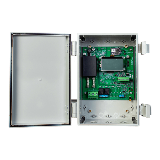
1.1 Specifications Model Number PC4R 90 VAC – 528 VAC Input Voltage Input Current -10 °C to 50 °C (-14 °F to 122 °F) Operating Temperature Range -20 °C to 60 °C (-4 °F to 140 °F) Storage Temperature 11.73” x 9.07” x 6.22” Dimensions (H x W x D) Enclosure Type NEMA 3R... -
Page 7: Mounting The Enclosure
INSTALLATION Install Tip Devices must be activated through the online portal before device will connect. Go to connect.phasetechnologies.com to activate new devices. 2.1 Mounting the Enclosure Each Phase Connect device comes with external mounting brackets and two sets of screws. Use the larger screws to fasten the mounting brackets to the enclosure as shown below. -
Page 8: Grounding The Device
Antenna Cable Figure 3 – Antenna Connection Install Tip A cell phone signal booster may be used to increase reception in remote areas. 2.3 Grounding the Device • Properly ground the system according to local electrical code. • Connect the ground terminal to the branch circuit or service ground conductor with an adequately sized conductor according to local electrical code. -
Page 9: Field Wiring Terminals
2.4 Field Wiring Terminals The Phase Connect will accept an incoming voltage range of 100 VAC – 480 VAC. Connect incoming power cables to L1 and L2, shown in Figure 4, and tighten to 10.5 lb-in, as shown in Table 1. CAUTION: Installations must comply with NEC and local electrical code requirements. - Page 10 CONTROL WIRING The Phase Connect is equipped with two AUX inputs and an analog input for monitoring equipment status. The device also contains two Normally Open/Normally Closed (NO/NC) relay outputs and an analog output for controlling equipment with a manual 4-20 mA signal. Refer to Table 2 for wire sizes and torque values.
-
Page 11: Detect Vfd Fault
3.1 Detect VFD Fault To set up the device to detect a VFD fault on a Phase Technologies drive, connect wires as shown in Figure 5 and set PROGRAM RELAY 1 to “0 = SYSTEM FAULT” on VFD. When the VFD has a fault, AUX 1 will be shown in the CLOSED position on the portal Dashboard. -
Page 12: Monitor 4-20 Ma Transducer Input
3.3 Monitor 4-20 mA Transducer Input To view the reading of a 4-20 mA transducer, connect wires from a 4-20 mA transducer to the device as shown in Figure 7. In the portal, this reading will be displayed under the 4-20 mA Input. -
Page 13: Vfd Run/Stop Control
3.4 VFD Run/Stop Control To give a Phase Technologies VFD a RUN/STOP command remotely, connect wires as shown and make sure the VFD settings match those shown in Figure 9. These are default settings, so no changes should need to be made. On the portal dashboard, toggle Relay 1 and hit Send Commands button. -
Page 14: Ma Output Control
3.6 4-20 mA Output Control CAUTION: If sending a 4-20 mA signal from a Phase Connect to a Phase Technologies VFD, wires must be connected to I1- and COM in VFD. Wiring to I1+ and I1- can damage the VFD control board and void warranty. To manually control the speed of a Phase Technologies VFD relative to a 4-20 mA signal, connect wires as shown in Figure 11. -
Page 15: Repeat 4-20 Ma Input Signal
3.7 Repeat 4-20 mA Input Signal CAUTION: If sending a 4-20 mA signal from a Phase Connect to a Phase Technologies VFD, wires must be connected to I1- and COM in VFD. Wiring to I1+ and I1- can damage the VFD control board and void warranty. Phase Connect allows users to control a VFD and monitor the input from the portal using a single transducer. -
Page 16: Initialization
OPERATION Install Tip Devices must be activated through the online portal before device will connect. Go to connect.phasetechnologies.com to activate new devices. The first connection process should take about 20 minutes but can take longer depending on cellular reception. 4.1 Initialization After power and control connections are made, turn power to the device ON so device can begin the connection procedure. -
Page 17: Creating An Account
PHASE CONNECT PORTAL 5.1 Creating An Account A Phase Connect Portal account is required to view and manage Phase Connect devices. and click “Sign up for an To create a portal account, go to connect.phasetechnologies.com Account.” Enter your information and click “Accept Terms and Submit.” If you already have an account, you will need to log in to access your devices. -
Page 18: Device Dashboard
AUX and relay labels, as well as to configure 4-20 mA Input and Output, see the Config page. Use the Alerts page to set up text and email notifications. The Records page can be used to keep a log of device history. The Settings page is used to manage subscription plans and billing information. -
Page 19: Device Readings
5.5 Device Readings The Device Readings box section is where you will see Aux 1, Aux 2, and 4-20 mA Input readings. Readings are sent from the device to the portal hourly and can be requested at any time by clicking the Refresh button. Refreshing the device readings will request new readings from the device and display them once received. -
Page 20: Manage Contacts
5.9 Manage Contacts Alerts can be customized to text or email contacts when an event of interest occurs. Manage Contacts is found in the Portal Navigation Pane. Contacts can be arranged into groups that can receive alert notifications. Use this to save time when setting up alert notifications if multiple contacts need to be notified. -
Page 21: Deactivating Device
incoming power to the device will need to be manually cycled OFF/ON before device will resume communication. To pause device communication, go to the Settings page of the device you would like to pause, and hit the Pause button at the bottom of the screen. Likewise, to un-pause device communication, click the Un-Pause button at the bottom of the settings page for the paused device. - Page 22 TROUBLESHOOTING PROBLEM POTENTIAL CAUSE SOLUTION Ensure incoming power is 100 Incorrect source voltage VAC – 480 VAC. Device not powering on Check fuses, located above L1 Blown fuses and L2 terminals. If damaged, replace with 500 V, 3.15 A fuses. Wait for at least one hour and check communication again.
- Page 23 WARRANTY INFORMATION LIMITED WARRANTY This Limited Warranty applies to the following Phase Technologies’ product lines: Phase Connect One Year Warranty Phase Connect devices are warranted against defects in material and workmanship. This warranty covers both parts and labor from the date of purchase from Phase Technologies.
- Page 24 Scan to download product information 222 Disk Dr, Rapid City, SD 57701 866-250-7934 – Toll Free 605-343-7934 – Main www.phasetechnologies.com...
Need help?
Do you have a question about the PHASE CONNECT PC4R and is the answer not in the manual?
Questions and answers