
Related Manuals for Johnson 3X


Summary of Contents for Johnson 3X
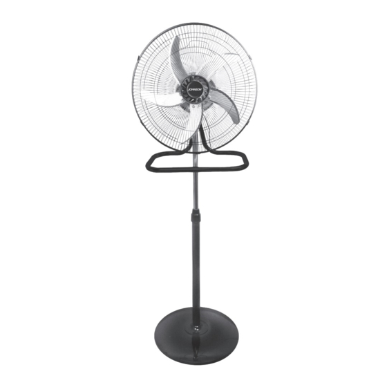
- Page 1 Ventilatore multifunzione, a piantana, da tavolo e da parete ISTRUZIONI D’USO Multifunction standing fan, wall fan, table fan and stand fan. INSTRUCTIONS FOR USE...
-
Page 2: Avvertenze Generali
AVVERTENZE GENERALI Conservate con cura il presente manuale e leggetene attentamente le avvertenze; esse forniscono importanti indicazioni riguar danti la sicurezza, l’uso immediato e futuro dell’apparecchio. ATTENZIONE: L’apparecchio può essere utiliz zato da bambini di 8 anni in su e da persone le cui capacità... - Page 3 pericoloso. Il costruttore non può essere con siderato responsabile per eventuali danni de rivanti da usi impropri, errati ed irragionevoli. L’installazione dovrà essere effettuata secon do le prescrizioni del costruttore. Una errata installazione può causare danni a persone, animali, cose, il costruttore non può esserne ritenuto responsabile.
- Page 4 di distribuzione elettrica. Utilizzando l’apparecchio per la prima volta, assicurarsi di aver tolto ogni etichetta o foglio di protezione, tranne quelle relative ai dati tec nici dell’apparecchio o quelle recanti informa zioni del prodotto. Non usare l’apparecchio se non funziona cor rettamente o se sembra danneggiato, control...
- Page 5 umide. Non usare l’apparecchio a piedi nudi. Non tirare l’apparecchio o il cavo per staccare la spina dalla presa. Non infilare alcun utensile o le dita fra le ma glie della griglia di protezione della ventola. Durante l’uso, l’apparecchio deve essere lon tano da qualsiasi oggetto o sostanza infiam...
- Page 6 Per pulire l’apparecchio usare solo un panno morbido e non abrasivo. Quando l’apparecchio, risulta inutilizzabile e si desidera eliminarlo, asportarne i cavi e smal tirlo presso un ente qualificato al fine di non contaminare l’ambiente. Verificare periodicamente il buono stato dell’apparecchio e dei componenti;...
- Page 7 nato su di una superficie liscia, piana e stabile. L’apparecchio non deve essere usato dopo una caduta se danneggiato. Utilizzare l’apparecchio solo con gli accessori forniti in dotazione, per non compromettere la sicurezza di impiego. Non coprire in alcun modo il dispositivo quan do in funzione.
- Page 8 riporlo nel suo imballo originale e metterlo in un luogo secco ed asciutto. Quando lo si usa per la prima volta dopo un lungo periodo di inutilizzo, controllare che il ventilatore sia pu lito e che la ventola giri liberamente (a disposi tivo non alimentato) senza alcun freno.
- Page 9 Componenti Q Tasselli A Griglia anteriore R Ganci per fissaggio a muro B Ventola S Base per uso da tavolo e da muro C Ghiera blocca griglia posteriore S1 Tubo centrale base D Griglia posteriore S2 Tubo destro base E Corpo motore S3 Tubo sinistro base F Selettore oscillazione T Viti fissaggio piedini in plastica...
- Page 11 MONTAGGIO VENTILATORE A PIANTANA 1 Inserire il tubo base (K) nel foro della base (N) e nel peso stabilizzatore (Y). Fare coincidere i fori di riferimento, inserire le 4 viti (O), posizionare i dadi (O) ed avvitare saldamente. Svitare la ghiera (J) del tubo base (K) ed infilare la copertura viti base (L), posizionarla correttamente e riavvitare la ghiera (J) sul tubo base (K).
- Page 12 Fig. 3 Fig. 4 Fig. 5 Fig. 6 Fig. 7...
- Page 13 MONTAGGIO VENTILATORE DA TAVOLO 7 Assemblare i tubi della base (S) innestandoli l’uno nell’altro, posizionare il tubo cen trale (S1) con i fori rivolti verso il basso ed inserire nel suo lato destro il tubo (S2) S2 è il tubo con i fori per fissare il supporto aggancio interruttore (Z), ed avvitare con la vite (T).
- Page 14 MONTAGGIO VENTILATORE A PARETE 10 Assemblare il corpo motore (E), la griglia posteriore (D), la ventola (B), la griglia an teriore (A), la base (S) come descritto nel paragrafo precedente (montaggio ventilatore da tavolo). 11 Scegliere l’inclinazione desiderata del gruppo motore (E) sulla base (S): Posizione 1: assicurarsi che la linguetta (DD) del corpo motore (E) sia alloggiata nella sede (1) della base (S) come da figura 12, per un flusso d’aria diretto verso il basso.
- Page 15 ISTRUZIONI PER L’USO Una volta che il ventilatore è stato completamente assemblato in una delle tre configu razioni, inserire la spina in una presa di corrente idonea a riceverla. Per avviare la ventilazione ruotare il selettore (G) su 1 – 2 o 3 corrispondenti alle 3 velo cità...
- Page 16 GENERAL SAFETY REQUIREMENTS Carefully read the requirements in this ma nual an keep in a safe piace. lt contains im portant instructions an the safety, use and fu ture of your appliance. ATTENTION: The appliance can be used by children aged 8 and over and by people whose physical, sensory or mental capacities are redu...
- Page 17 to the manufacturer’s requirements. Incorrect installation can cause damage to people, ani mals, things, the manufacturer cannot be held responsible. The safety of electrical equipment is guaranteed only if they are connected to an electrical system equipped with suitable groun ding in accordance with the current standards in force on electrical safety.
- Page 18 properly or if it appears damaged, check that the power supply cable is in good condition; in case of doubt, contact an authorized technical assistance center. If the appliance is equipped with air vents, make sure that they are never blocked, even partially, and that no type of object is inserted.
- Page 19 Disconnect the plug from the socket when the appliance is not in use and before carrying out any cleaning or maintenance. The power cable must be unrolled along its entire length in order to avoid overheating. The power cable must not be placed near heat sources and / or sharp surfaces.
- Page 20 supply. Do not use the appliance if it does not work properly or if it appears damaged; if in doubt, contact qualified personnel. It is absolutely forbidden to disassemble or re pair the appliance due to the danger of electric shock;...
- Page 21 Do not power the device without having first assembled it correctly, following the instruc tions in this manual. Place the fan at an adequate distance from sur rounding objects or walls so that its operation cannot cause accidental damage. Do not leave the appliance unattended for long periods during operation.
- Page 22 ATTENTION: The plastic parts of the product are not covered by warranty. lf the product contains glass parts, they are not covered by the warranty. ATTENTION: Damage to the power cable due to wear is not covered by the warranty; any repairs are therefore the responsibility of the owner.
- Page 23 Components Q Dowels A Front grille R Hooks for wall fixing B Fan S Base for table and wall use C Rear grille locking ring S1 Base center tube D Rear grille S2 Right base tube E Motor body S3 Left base tube F Swing selector T Plastic feet fixing screws G Speed selector...
- Page 25 FLOOR FAN ASSEMBLY 1 Insert the base tube (K) into the hole in the base (N) and into the stabilizer weight (Y). Make the reference holes coincide, insert the 4 screws (O), position the nuts (O) and tighten firmly. Unscrew the ring nut (J) of the base tube (K) and insert the base screw cover (L), position it correctly and screw the ring nut (J) back onto the base tube (K).
- Page 26 Fig. 3 Fig. 4 Fig. 5 Fig. 6 Fig. 7...
- Page 27 TABLE FAN ASSEMBLY 7 Assemble the tubes of the base (S) by inserting them into each other, position the central tube (S1) with the holes facing downwards and insert the tube (S2) on its right side S2 is the tube with the holes to fix the switch coupling support (Z), and tighten with the screw (T).
- Page 28 WALL FAN ASSEMBLY 10 Assemble the motor body (E), the rear grill (D), the fan (B), the front grill (A), the base (S) as described in the previous paragraph (table fan assembly). 11 Choose the desired inclination of the motor unit (E) on the base (S): Position 1: make sure that the tab (DD) of the motor body (E) is housed in the seat (1) of the base (S) as shown in Figure 12, for a downward flow of air.
- Page 29 IEC 60879: 1986 (corr. 1992) Standby power consumption 0,42 Fan sound power level 63,93 dB(A) Maximum air velocity 3,46 meters/sec Seasonal electricity consumption 26,01 KWh/a Contact details for obtaining more information JOHNSON S.r.l V.le Kennedy, 596 21050 Marnate (VA) Italy...
- Page 31 Garanzia La durata della garanzia decorre dalla data di acquisto dell’apparecchio, comprovata dal timbro del rivenditore e cessa dopo il periodo prescritto anche se l’apparecchio non è stato usato. Ri entrano nella garanzia tutte le sostituzioni o riparazioni che si rendessero necessarie per difetti di materiale o di fabbricazione.
- Page 32 S.r.l. V.le Kennedy, 596 - 21050 Marnate (VA) Italy - internet: www.johnson.it - e-mail: com@johnson.it +39 0331 389007 Mod. 3X Mod. 3X Compilare all’atto dell’acquisto DATA ACQUISTO PURCHASE DATE Check before purchasing DATE D’ A CHAT Remplir au moment del’achat...
Need help?
Do you have a question about the 3X and is the answer not in the manual?
Questions and answers