Advertisement
Quick Links
Advertisement

Related Manuals for Kogan KASPACRAILA


Summary of Contents for Kogan KASPACRAILA
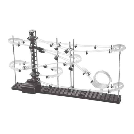
- Page 1 DIY MARBLE RUN ROLLER COASTER KASPACRAILA...
- Page 3 SAFETY & WARNNINGS • Ensure all safety instructions are read and understood before use. Retain this user guide for future reference. • WARNING: Choking hazard. This toy contains small parts. It is not suitable for children under 5 without parental supervision. •...
- Page 4 COMPONENTS Parts: B1 Base (x3) S1 Shaft (x9) R1 Rail (5m) A1 Arm (x5 + spare) A2 Arm Stand A A3 Arm Sheath A4 Arm Stand B A5 Arm Wrench (x5 + spare) (x5 + spare) (x5 + spare) (x10 + spare) A6 Rail Stand G1 Gear Box F1 Fork...
- Page 5 B2 Base Holder B3 Base Holder G2 Gear Box Stand Steel Ball (x2) (large) (x2) (small) (x2) (x2) Rail Joint (x2) Tools Required: Pliers Marker...
- Page 6 ASSEMBLY Step 1: Base assembly • Join the 3 Bases (B1) together. • Secure the Bases using the Base Holders (B2) (B3) in the positions shown. (B2) Base holder (big) (B3) Base holder (small) (B1) Base...
- Page 7 Step 2: Arm assembly • Connect Arm Stand B (A4) to the Arm Sheath (A3). • Connect the Arm Sheath (A3) to Arm Stand A (A2). • Insert Arm (A1) into Arm Stand A (A2) (Figure 1). • Insert the Arm Wrench (A5) and turn it 90° counter-clockwise to lock the Arm (A1) in place (Figure 2).
- Page 8 Step 3: Elevator installation • Insert a Shaft (S1) into the Gear Box (G1) (Figure 3). • Insert 12 Elevator Helix (E1) pieces onto the Shaft (S1). Ensure the helix pieces are inserted correctly with no space left between the Gear Box (G1) and the Helix (E1) (Figure 4).
- Page 9 • Insert 3 Shafts (S1) into the holes on the Gear Box (G1) (Figure 5). • Insert the 3 Elevator Rings (E2) onto the Shafts (S1) in the positions shown. Ensure Elevator Rings (E2) are inserted with the ringways convex side up (Figure 6). (S1) Shaft The ringways must be convex...
- Page 10 • Attach the Elevator Cover (E3) to the shafts (Figure 7). • Attach 3 of the Rail Stands (A6) to the Elevator Rings (E2) in the positions shown (Figure 8). • Attach an Elevator Stand (E4) to each of the Elevator Rings (E2) (Figure 9). (E3) Elevator Cover (A6) Rail Stand (A6) Rail Stand...
- Page 11 Step 4: Rail Stands • Attach 3 Rail Stands (A6) to the Fork (F1) (Figure 10). • Attach 2 Rail Stands (A6) to the each of the Corners (C1) (C2) (Figure 11). • Attach 2 Rail Stands (A6) to the Loop (L1) (Figure 12). (C1) (C2) Corners (F1) Fork (A6) Rail Stand...
- Page 12 Step 5: Shaft, Corner & Arm Installation Attach the 5 shafts (S1) to base in the positions shown (Figure 13 & 14). Elevator Loop Figure 13 Loop Elevator Figure 14...
- Page 13 Corners: • The corners are marked as shown (Figure 15) to help distinguish between Corner A (C1) and Corner B (C2). • Each corner piece has three different mounting positions for attaching onto the shafts. Pay close attention to the orientation shown in (Figure 17) to ensure correct assembly.
- Page 14 Attaching the Arms & Corners to the Shafts: Attach the Arm assemblies and Corner pieces (C1) (C2) to the Shafts (S1). Pay close attention to the orientation of the mounting positions (Figure 17). Note: Shafts B & C are joined together with a Corner A (C1) piece. BACK DOWN FRONT...
- Page 15 Step 6: Attaching the Elevator & Loop • Attach the Gear Box Stand (G2) to the underside of the Gear Box (G1) (Figure 18). • Attach the Elevator to the base in the position shown (refer to Figures 13 & 14). •...
-
Page 16: Rail Installation
RAIL INSTALLATION Cutting the Rails to Length • Following the table below measure and mark the rails to the appropriate lengths. • Use pliers or side cutters to cut the rails in the marked positions. Note: To avoid confusion and ensure correct assembly, it is recommended to clearly label each rail. - Page 17 Rails (R1) can be joined together using a Rail Joint (R2) as shown below. (R2) Rail Joint (R1) Rail (R1) Rail Assembly: • Insert the rails into the notches in the Arms (A1) (Figure 20). Adjust the position and angle of the arm as required, before installing the rails. •...
- Page 18 Inclines: • Ensure the rails are kept parallel to each other (Figure 21). • Ensure the inclines are smooth without kinks or waves (Figure 22). Figure 21 Figure 22...
-
Page 19: Installation
Installation Step 1: • Insert 2 Rails (h) between the Elevator and Corner B (C2). • Insert 2 Rails ( j) between the Elevator and Corner B (C2). • Insert 2 Rails (b) between the Elevator and Corner B (C2). ( j) - Page 20 Step 2: • Insert 2 Rails (g) between the Loop (L1) and Fork (F1). • Insert 2 Rails (a) between the Loop (L1) and Corner B (C2). • Insert 2 Rails (i) between Corner B (C2) and the Elevator entry. Note: Ensure the rail is close to the helix at the Elevator entry so the ball runs smoothly.
- Page 21 Step 3: • Insert 2 Rails (d) between Corner A (C1) and the Fork (F1). • Insert 2 Rails (f) between Corner A (C1) and Corner B (C2). • Insert 2 Rails (e) between Corner B (C2) and Corner A (C1). •...
-
Page 22: Installation Tips
Installation tips: Refer to the below image when inserting the Rails (R1) into the Fork (F1). The Corners may flex slightly when the steel balls run through it. The Corner Stands (C3) can be installed to help avoid this problem. Corner (C3) Corner Stand... - Page 23 NOTES...
- Page 24 Need more information? We hope that this user guide has given you the assistance needed for a simple set-up. For the most up-to-date guide for your product, as well as any additional assistance you may require, head online to help.kogan.com...
Need help?
Do you have a question about the KASPACRAILA and is the answer not in the manual?
Questions and answers