Advertisement
Quick Links
Advertisement

Subscribe to Our Youtube Channel
Related Manuals for Kogan KASPCRLGLWB


Summary of Contents for Kogan KASPCRLGLWB
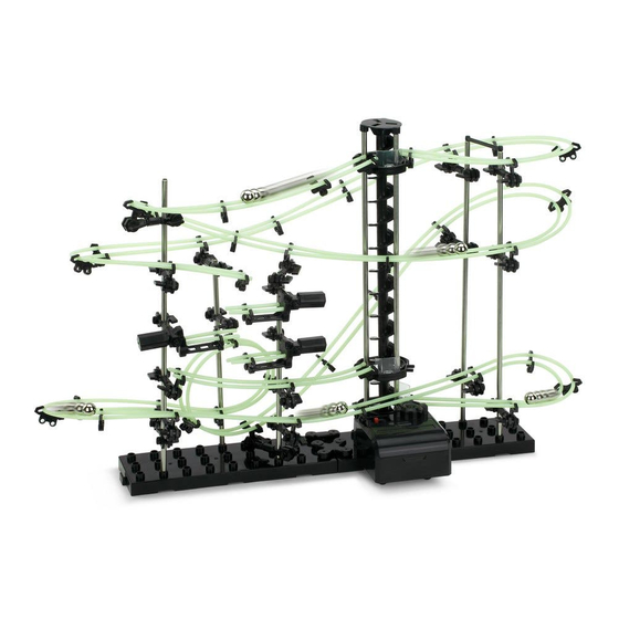
- Page 1 DIY MARBLE RUN ROLLER COASTER KASPCRLGLWB...
- Page 3 SAFETY & WARNNINGS • Ensure all safety instructions are read and understood before use. Retain this user guide for future reference. • WARNING: Choking hazard. This toy contains small parts. It is not suitable for children under 5 without parental supervision. •...
- Page 4 COMPONENTS Parts: B1 Base (x2) S1 300mm S2 200mm R1 Rail (10m) Shaft (x7) Shaft (x2) A1 Arm (x17) A2 Arm Stand A A3 Arm Sheath (x20) A4 Arm Stand B (x20) (x17) A5 Arm Wrench (x37) A6 Rail Stand (x40) G1 Gear Box E1 Elevator Helix (x12) E2 Elevator Ring (x3)
- Page 5 B2 Base Holder B3 Base Holder S3 Shaft Joint G2 Gear Box Stand (Large) (Small) Steel Ball (x2) Rail Joint (x4) Tools Required: Pliers Marker...
- Page 6 ASSEMBLY Step 1: Base assembly • Join the Bases (B1) together. • Secure the Bases using the Base Holders (B2) (B3) in the positions shown. (B2) Base holder (large) (B3) Base holder (small) (B1) Base...
- Page 7 Step 2: Arm assembly • Connect Arm Stand B (A4) to the Arm Sheath (A3). • Connect the Arm Sheath (A3) to Arm Stand A (A2). • Insert Arm (A1) into Arm Stand A (A2) (Figure 1). • Insert the Arm Wrench (A5) and turn it 90° counter-clockwise to lock the Arm (A1) in place (Figure 2).
- Page 8 Step 3: Elevator installation • Insert a 300mm Shaft (S1) into the Gear Box (G1) (Figure 3). • Insert 12 Elevator Helix (E1) pieces onto the 300mm Shaft (S1). Ensure the Helix pieces are inserted correctly with no space left between the Gear Box (G1) and the Helix (E1) (Figure 4).
- Page 9 • Insert x3 300mm Shafts (S1) into the holes on the Gear Box (G1) (Figure 5). • Insert the 3 Elevator Rings (E2) onto the 300mm Shafts (S1) in the positions shown. Ensure Elevator Rings (E2) are inserted with the ringways convex side up (Figure 6). (S1) 300mm Shafts The ringways must be convex...
- Page 10 • Attach the Elevator Cover (E3) to the shafts (Figure 7). • Attach an Elevator Stand (E4) to each of the Elevator Rings (E2) (Figure 8). • Attach 4 of the Rail Stands (A6) to the Elevator Rings (E2) in the positions shown (Figure 9).
- Page 11 Step 4: Seesaw Assembly • Attach a Rail Stand (A6) to the Seesaw (F1). • Cut 2 lengths of the Rail (R1) approximately 55mm long and then attach them to the Seesaw (F1) in the position shown (Figure 10). 55mm F1 Seesaw (A6) Rail Stand Figure 10...
- Page 12 Step 5: Shaft, Seesaw & Arm Installation Arms: • To secure the Arm assembly to the shafts, insert the shaft into Arm Stand B (A4). • Secure the shaft in place by inserting an Arm Wrench (A5) and rotating 90° counter-clockwise (Figure 12).
- Page 13 (F1) Arm Seesaw (F1) (F1) Figure 13 • Attach the 5 shafts (S1) to base in the positions shown (Figure 14). • Connect D & E together using the Shaft Joint (S3). Back (S3) Shaft Joint Front Elevator Figure 14...
- Page 14 Step 6: Attaching the Elevator • Attach the Gear Box Stand (G2) to the underside of the Gear Box (G1) (Figure 15). • Attach the Elevator to the base in the position shown (refer to Figure 14). (G1) Gear Box Insert into the holes on base (G2) Gear Box Stand...
-
Page 15: Rail Installation
RAIL INSTALLATION Rails (R1) can be joined together using a Rail Joint (R2) as shown below. (R2) Rail Joint (R1) Rail (R1) Rail Assembly: • Insert the rails into the notches in the Arms (A1) (Figure 16). Adjust the position and angle of the arm as required, before installing the rails. - Page 16 Inclines: • Ensure the rails are kept parallel to each other (Figure 17). • Ensure the inclines are smooth without kinks or waves (Figure 18). Figure 17 Figure 18...
- Page 17 Corners: • The outside rail will need to be raised slightly when creating corners, to ensure the ball doesn’t leave the track (Figure 19). • Use dips to allow the ball to slow down before approaching corners (Figure 20). Figure 19 Dip before entering the corner Figure 20...
- Page 18 Loops: • The decline height leading into the loop must be twice that of the loop (inner diameter) to ensure smooth running (Figure 21). Note: The loop should be a complete circle (Figure 22). • A larger loop should not follow a smaller loop. Side Elevation Loop Diameter Decline height...
- Page 19 Elevator: • The rail should enter the Elevator smoothly and be close to the Elevator Helix (E1) to ensure proper operation (Figure 23). • The angle of the rails at Elevator exit should be as shown below (Figure 24). Entry Entry Figure 23 Figure 24...
- Page 20 Installation: Refer to Figures 25 & 26 for correct rail placements. Shafts Seesaw Figure 25 Elevator Figure 26...
- Page 21 Step 1: • Measure and cut x2 245cm lengths of Rail (R1). • Install the Rails (R1) referring to Figures 27 & 28. Note: The letters and numbers correspond to Figures 25 & 26. Path continued in next image Elevator Exit Figure 27...
- Page 22 Loop Continued from previous image Elevator Entry Figure 28...
- Page 23 Step 2: • Measure and cut x2 105cm lengths of Rail (R1). • Install the Rails (R1) between the Elevator exit J-3 and the upper Seesaw (F1) referring to Figure 29. Figure 29...
- Page 24 Step 3: • Measure and cut x2 26cm lengths of Rail (R1). • Install the Rails (R1) between the lower Seesaw (F1) and Elevator Entry J-2 (Figure Figure 30...
-
Page 25: Reference Images
REFERENCE IMAGES... - Page 26 NOTES...
- Page 28 Need more information? We hope that this user guide has given you the assistance needed for a simple set-up. For the most up-to-date guide for your product, as well as any additional assistance you may require, head online to help.kogan.com...
Need help?
Do you have a question about the KASPCRLGLWB and is the answer not in the manual?
Questions and answers