Table of Contents
Advertisement
Quick Links
Advertisement
Chapters
Table of Contents

Related Manuals for Bluetechnix Sentis3D-M530


Summary of Contents for Bluetechnix Sentis3D-M530
- Page 1 Sentis3D-M530 Hardware User Manual Version 2...
- Page 2 Contact Bluetechnix Waidhausenstraße 3/19 A-1140 Vienna AUSTRIA office@bluetechnix.com http://www.bluetechnix.com Date: 2016-04-27 Template No.: 900-306 / A...
-
Page 3: Table Of Contents
Table of Contents General Information .......................... 6 Symbols Used ........................... 6 Certification ..........................6 Safety instructions ........................7 Electrical connection ......................... 7 Introduction ............................8 Overview ........................... 8 Key Features ..........................8 General Description .......................... 9 Functional Description ......................9 PCB description ........................ - Page 4 Bottom View ..........................20 Side View ..........................20 Product History ..........................21 Version Information ......................... 21 8.1.1 Sentis3D-M530 ........................ 21 Anomalies ..........................21 Document Revision History ......................22 List of Figures and Tables ......................23 Template No.: 900-306 / A...
- Page 5 Bluetechnix takes no liability for any damages and errors causing of the usage of this board. The user of this board is responsible by himself for the functionality of his application. He is allowed to use the board only if he has the qualification.
-
Page 6: General Information
Version 2 General Information This guide applies to the Sentis3D-M530 camera platform from Bluetechnix. Follow this guide chapter by chapter to set up and understand your product. If a section of this document only applies to certain camera parts, this is indicated at the beginning of the respective section. -
Page 7: Safety Instructions
Hardware User Manual - Sentis3D-M530 Last change: 27 April 2016 Version 2 Safety instructions Important This manual is part of the device and contains information and illustrations about the correct handling of the device and must be read before installation or use. Observe the operating instructions. -
Page 8: Introduction
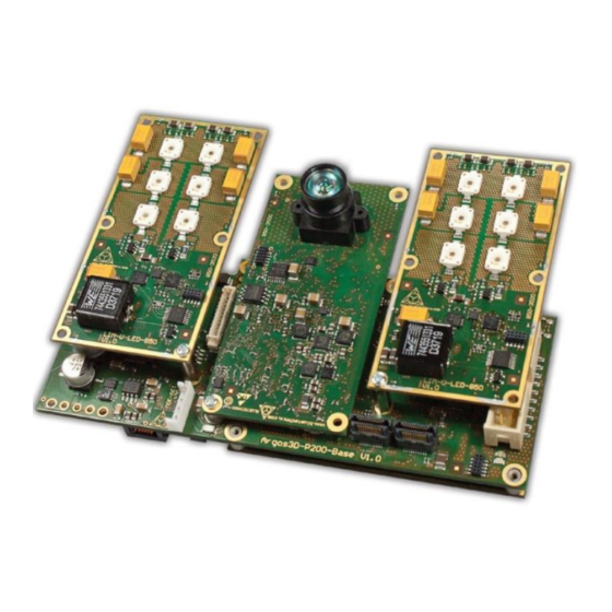
The Sentis3D-M530 is a depth sensor module, developed by Bluetechnix, operating on the Time-of-Flight (ToF) principle. The Sentis3D-M530 is based on the ToF sensor IRS1020/1125 from Infineon and Freescale i.MX6 processor. The camera consists of different modules from Bluetechnix like the TIM-U-IRS1020, LIM-u- LED-850 and CM-i.MX6x. -
Page 9: General Description
The two LIM-u-LED-850 are mounted on the Extension-Board Interfaces The following chapters describes the interfaces on the Sentis3D-M530-Baseboard. 3.3.1 Power connector The Sentis3D-M530 must be powered by an external 18V-30V power supply connected to the 2.5mm EH- connector (see chapter 6.1). Bluetechnix © Page 9 | 23... -
Page 10: Gbit-Ethernet
3.3.6 RGB LED A RGB LED is available on the Extension-Board and can be used to show the state of the Sentis3D-M530 (component (f) in Figure 6-1). The RGB LED is controlled by a Toshiba LED driver (TCA62724FMG(O,EL)) connected though the I2C2 interface with the CM-i.MX6x. -
Page 11: Hardware Installation
Version 2 Hardware installation Mounting The Sentis3D-M530-Baseboard provides 4 x M3 mounting holes to fix it on the enclosure. The positions of the mounting holes is shown in figure 7.1 (3.2mm holes). Note: The mounting holes must be electrically connected to the enclosure using metallic screws! The LIM modules mounted on the Sentis3D-M530-Baseboard must be fixed to a heatsink or to the enclosure. -
Page 12: Lenses And Objective
Lenses and objective The Sentis3D-M530 is equipped with a 80° objective for the TIM module, 90° objective for the 2D sensor and 90° lenses for the LIM modules. Other objectives/lenses can be provided by Bluetechnix on request. -
Page 13: Figure 4-2 Possible Optical Isolation (Side View)
Hardware User Manual - Sentis3D-M530 Last change: 27 April 2016 Version 2 90° 90° 80° Figure 4-2 Possible optical isolation (Side view) Figure 4-3 Possible optical isolation (Top view) Bluetechnix © Page 13 | 23... -
Page 14: Sensor Orientation
Hardware User Manual - Sentis3D-M530 Last change: 27 April 2016 Version 2 Sensor Orientation See Hardware User Manual of the TIM-U-IRS1020. Bluetechnix © Page 14 | 23... -
Page 15: Specifications
Hardware User Manual - Sentis3D-M530 Last change: 27 April 2016 Version 2 Specifications Electrical Specifications 5.1.1 Operating Conditions Symbol Parameter Typical Unit Input supply voltage Input current Operating Temperature °C Storage Temperature °C FITP Frame-rate Integration Time Product Table 5-1 Electrical characteristics Depends on cooling mechanism. -
Page 16: Connector Description
Hardware User Manual - Sentis3D-M530 Last change: 27 April 2016 Version 2 Connector Description Marks Pin #1 Figure 6-1 Connectors of the Sentis3D-M530 (top view with transparent LIM-u-LED-850) Figure 6-2 Front panel vew Bluetechnix © Page 16 | 23... -
Page 17: Power Connector (A)
GBit Ethernet Connector (b) This standard RJ45 connector provides a 10/100/1000 Base-T interface to the Sentis3D-M530. Extension Connector (c) The Mini-DIN 8 connector provides several interfaces to connect the Sentis3D-M530 to external devices. Figure 6-3 Mini-DIN8 pin out Signal Type... -
Page 18: Jtag Connector (D)
Hardware User Manual - Sentis3D-M530 Last change: 27 April 2016 Version 2 Note: To use the output functionality of the GPIO pin an external pullup resistor is necessary. This pullup must be designed for a minimum current of 13mA. (e.g 1k5 pullup to 20V) -
Page 19: Mechanical Outline
Hardware User Manual - Sentis3D-M530 Last change: 27 April 2016 Version 2 Mechanical Outline A 3D STEP model of the Sentis3D-M530 can be provided by Bluetechnix on request. Top View Figure 7-1 Top View of the Sentis3D-M530-Baseboard Bluetechnix © Page 19 | 23... -
Page 20: Bottom View
Hardware User Manual - Sentis3D-M530 Last change: 27 April 2016 Version 2 Bottom View Figure 7-2 Bottom View of the Sentis3D-M530-Baseboard Side View Figure 7-3 Side view of the Sentis3D-M530-Baseboard Bluetechnix © Page 20 | 23... -
Page 21: Product History
Product History Version Information 8.1.1 Sentis3D-M530 Version State Release 1.0.0 X-Grade April 2016 Table 8-1 Overview Sentis3D-M530 product changes Anomalies Version Date Description V1.0.0 2016 04 22 No anomalies reported yet Table 8-2 Product anomalies Bluetechnix © Page 21 | 23... -
Page 22: Document Revision History
Hardware User Manual - Sentis3D-M530 Last change: 27 April 2016 Version 2 Document Revision History Version Date Document Revision 2016 04 22 First release V1.0 of the document 2016 04 27 Subtitle corrected Table 9-1 Revision history Bluetechnix © Page 22 | 23... -
Page 23: A List Of Figures And Tables
Figure 4-2 Possible optical isolation (Side view) ....................13 Figure 4-3 Possible optical isolation (Top view) ....................13 Figure 6-1 Connectors of the Sentis3D-M530 (top view with transparent LIM-u-LED-850) ......16 Figure 6-2 Front panel vew ..........................16 Figure 6-3 Mini-DIN8 pin out ..........................17 Figure 7-1 Top View of the Sentis3D-M530-Baseboard ...................
Need help?
Do you have a question about the Sentis3D-M530 and is the answer not in the manual?
Questions and answers