Table of Contents
Advertisement
Quick Links
Advertisement
Chapters
Table of Contents

Related Manuals for Bluetechnix Sentis ToF-P510


Summary of Contents for Bluetechnix Sentis ToF-P510
- Page 1 Sentis ToF - P510 Hardware User Manual Version 6 *former named Sentis-ToF-P510...
- Page 2 Contact Bluetechnix Waidhausenstraße 3/19 A-1140 Vienna AUSTRIA office@bluetechnix.com http://www.bluetechnix.com Date: 2016-04-08 Template No.: 900-306 / A...
-
Page 3: Table Of Contents
Table of Contents General Information .......................... 6 Symbols Used ........................... 6 Certification ..........................6 Safety instructions ........................7 Electrical connection ......................... 7 Introduction ............................8 Overview ........................... 8 Key Features ..........................8 General Description .......................... 9 Functional Description ......................9 PCB description ........................ - Page 4 Mechanical Outline ......................... 19 Top View ..........................19 Bottom View ..........................20 Side View ..........................20 Product History ..........................21 Version Information ......................... 21 8.1.1 Sentis3D-M520 ........................ 21 Anomalies ..........................21 Document Revision History ......................22 List of Figures and Tables ......................23 Template No.: 900-306 / A...
- Page 5 Bluetechnix takes no liability for any damages and errors causing of the usage of this board. The user of this board is responsible by himself for the functionality of his application. He is allowed to use the board only if he has the qualification.
-
Page 6: General Information
Version 6 General Information This guide applies to the Sentis3D-M520 camera platform from Bluetechnix GmbH. Follow this guide chapter by chapter to set up and understand your product. If a section of this document only applies to certain camera parts, this is indicated at the beginning of the respective section. -
Page 7: Safety Instructions
Device of protection class III (PC III). The electric supply must only be made via PELV circuits. The device must only be powered by a limited energy source (≤ 30V; ≤ 8A; ≤ 100VA). Disconnect power before connecting the unit. Bluetechnix © Page 7 | 23... -
Page 8: Introduction
Introduction Overview The Sentis3D-M520 is a depth sensor module, developed by Bluetechnix, operating on the Time-of-Flight (ToF) principle. The Sentis3D-M520 is based on the ToF sensor 19k-S3 of PMDtec and Freescale i.MX6 processor. The camera consists of different modules from Bluetechnix like the TIM-uP-19k-S3-Spartan-6, LIM-u-LED-850 and CM-i.MX6x. -
Page 9: General Description
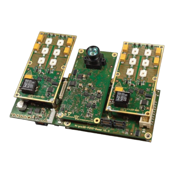
The two LIM-u-LED-850 are mounted on the Extension-Board Interfaces The following chapters describes the interfaces on the Sentis3D-M520-Baseboard. 3.3.1 Power connector The Sentis3D-M520 must be powered by an external 18V-30V power supply connected to the 2.5mm EH- connector (see chapter 6.1). Bluetechnix © Page 9 | 23... -
Page 10: Gbit-Ethernet
A buzzer is available on the Extension-Board and can be used to provide an audible feedback to the user (component (g) in Figure 6-1). The buzzer is connected to the pin DISP0.DAT9 of the CM-i.MX6x. Bluetechnix © Page 10 | 23... -
Page 11: Hardware Installation
The LIM modules mounted on the Sentis3D-M520-Baseboard must be fixed to a heatsink or to the enclosure. For more information about the LIM modules see the Hardware User Manual of the LIM-U-LED- 850 available from Bluetechnix website. The mounting holes are also visible on the 3D STEP model of the Sentis3D-M520 camera. -
Page 12: Lenses And Objective
Lenses and objective The Sentis3D-M520 is equipped with a 90° objective for the TIM module, 90° objective for the 2D sensor and 90° lenses for the LIM modules. Other objectives/lenses can be provided by Bluetechnix on request. Note: Be aware that using different objectives and lenses for other FOVs leads to different objective/lenses height relative to the 3D and 2D sensor. -
Page 13: Figure 4-2 Possible Optical Isolation (Side View)
Hardware User Manual - Sentis ToF - P510 Last change: 8 April 2016 Version 6 90° 90° 90° Figure 4-2 Possible optical isolation (Side view) Figure 4-3 Possible optical isolation (Top view) Bluetechnix © Page 13 | 23... -
Page 14: Sensor Orientation
Hardware User Manual - Sentis ToF - P510 Last change: 8 April 2016 Version 6 Sensor Orientation See Hardware User Manual of the TIM-UP-19k-S3 USB 2.0 PVI available from Bluetechnix website. Bluetechnix © Page 14 | 23... -
Page 15: Specifications
EN55022 class A, EN55024:2010 Only pre-compliance measurements according to the above stated normative will be performed on the system. The customer responsible for the final product is also responsible to fulfill all regulations requested by law. Bluetechnix © Page 15 | 23... -
Page 16: Connector Description
Hardware User Manual - Sentis ToF - P510 Last change: 8 April 2016 Version 6 Connector Description Marks Pin #1 Figure 6-1 Connectors of the Sentis3D-M520 (top view with transparent LIM-u-LED-850) Figure 6-2 Front panel vew Bluetechnix © Page 16 | 23... -
Page 17: Power Connector (A)
External Light modulation signal, differential, positive MOD_N Output External Light modulation signal, differential, negative GPIO In-/Output General purpose I/O (galvanic isolated) max. 50 V GPIO_Ref_GND Power GPIO reference Ground (galvanic isolated) Table 6-1: Power connector pinout Bluetechnix © Page 17 | 23... -
Page 18: Jtag Connector (D)
Table 6-2: Mating connector JTAG Connector (d) The JTAG interface of the CM-i.MX6x is connected to the 20-pin 2.54mm header connector. The JTAG connector is compliant with any ARM JTAG Emulator. (e.g ARM DSTREAM). Bluetechnix © Page 18 | 23... -
Page 19: Mechanical Outline
Hardware User Manual - Sentis ToF - P510 Last change: 8 April 2016 Version 6 Mechanical Outline A 3D STEP model of the Sentis3D-M520 can be provided by Bluetechnix on request. Top View Figure 7-1 Top View of the Sentis3D-M520-Baseboard Bluetechnix ©... -
Page 20: Bottom View
Hardware User Manual - Sentis ToF - P510 Last change: 8 April 2016 Version 6 Bottom View Figure 7-2 Bottom View of the Sentis3D-M520-Baseboard Side View Figure 7-3 Side view of the Sentis3D-M520-Baseboard Bluetechnix © Page 20 | 23... -
Page 21: Product History
Last change: 8 April 2016 Version 6 Product History Version Information 8.1.1 Sentis3D-M520 Version Component Type 1.0.0 Bluetechnix TIM-uP-19k-S3 V2.0 Bluetechnix LIM-U-LED-850 V2.0 CM-i.MX6Q Bluetechnix CM-i.MX6Q-C-I-Q24S2048F2N4096 V1.2 5V Controller Texas Instruments LM25116MH/NOPB Table 8-1 Overview Sentis3D-M520 product changes Anomalies Version Date Description V1.0... -
Page 22: Document Revision History
2014 12 12 Added information about external pullup resistor on external GPIO 2015 03 04 Added GPIO_Ref to pin 8 of Mini Din 8 connector 2016 04 08 Renaming camera in Sentis3D-M520 Table 9-1 Revision history Bluetechnix © Page 22 | 23... -
Page 23: A List Of Figures And Tables
Table 5-1 Electrical characteristics ........................15 Table 6-1: Power connector pinout ........................17 Table 6-2: Mating connector ..........................18 Table 8-1 Overview Sentis3D-M520 product changes ..................21 Table 8-2 Product anomalies ..........................21 Table 9-1 Revision history ..........................22 Bluetechnix © Page 23 | 23...
Need help?
Do you have a question about the Sentis ToF-P510 and is the answer not in the manual?
Questions and answers