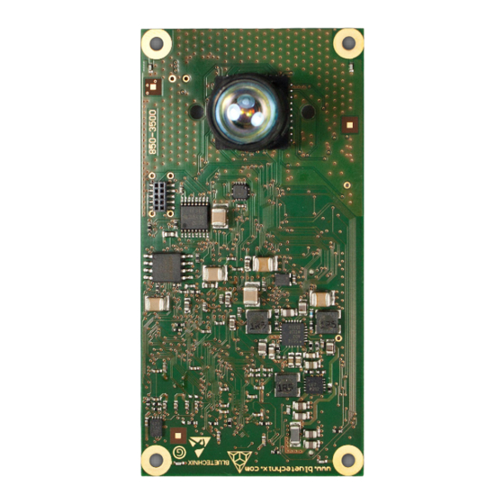
Table of Contents
Advertisement
Quick Links
Advertisement
Chapters
Table of Contents

Summary of Contents for Bluetechnix TIM-UP-19k-S3-Spartan 6
- Page 1 TIM-UP – 19k-S3-Spartan 6 V2.0.0 Software User Manual Version 5...
- Page 2 Contact Bluetechnix Waidhausenstraße 3/19 A-1140 Vienna AUSTRIA office@bluetechnix.com http://www.bluetechnix.com Date: 2014-08-19 Template No.: 900-306 / A...
-
Page 3: Table Of Contents
Table of Contents General Information .......................... 5 Symbols Used ........................... 5 Overview ............................6 Interfacing ............................7 General Data Format ......................... 7 USB Interface ..........................8 ISM / I C Interface ........................8 3.3.1 C Configuration Interface ....................8 3.3.2 ISM Data Interface ...................... - Page 4 Bluetechnix takes no liability for any damages and errors causing of the usage of this board. The user of this board is responsible by himself for the functionality of his application. He is allowed to use the board only if he has the qualification.
-
Page 5: General Information
General Information This guide applies to the TIM - 19k-S3-Spartan6 module from Bluetechnix GmbH. Follow this guide chapter by chapter to set up and understand your product. If a section of this document only applies to certain camera parts, this is indicated at the beginning of the respective section. -
Page 6: Overview
- 19k-S3-Spartan6 module and describes the firmware dependent interfaces. This document applies to firmware version v2.0.0 (0x19082014) For a hardware compatibility list please refer to our support site. Software and documentation https://support.bluetechnix.at/wiki/TIM-UP-19k-S3-Spartan6 Template No.: 900-306 / A Page 6 | 19... -
Page 7: Interfacing
For a complete description of the header data refer to our support site. https://support.bluetechnix.at/wiki/PMDSDK_/_PMDMDK_User_Manual #Source_Data_Container_Header The data containers hold the pixel information configured in the calculation mode register. By default, three data containers are configured. -
Page 8: Usb Interface
- 19k-S3-Spartan6 module over USB, a powerful Software Development Kit is provided. The SDK runs under Linux and Windows. Refer to our support site for downloading the SDK and for additional information and documentation. Software and documentation https://support.bluetechnix.at/wiki/TIM-UP-19k-S3-Spartan6 ISM / I C Interface 3.3.1 C Configuration Interface The TIM - 19k-S3-Spartan6 module can be configured using an I²C connection. -
Page 9: Ism Data Interface
Software User Manual - TIM-UP – 19k-S3-Spartan 6 Last change: 19 August 2014 Version 5 5 Register Description 3.3.2 ISM Data Interface When configured to stream data over ISM in free run mode, the TIM - 19k-S3-Spartan6 module starts transferring frames automatically and can only be interrupted by switching to manual trigger mode. -
Page 10: Hardware Connector
Software User Manual - TIM-UP – 19k-S3-Spartan 6 Last change: 19 August 2014 Version 5 Hardware Connector The following table shows the pin-out of the 100-pin TIM connector: Pin # Type Signal name Description ISM.nDE ISM Output enable: 0: ISM bus enabled, 1: ISM bus high Z Power ground ISM.D7 ISM Data Bit 7 (MSB) - Page 11 Software User Manual - TIM-UP – 19k-S3-Spartan 6 Last change: 19 August 2014 Version 5 Pin # Type Signal name Description UART.TX UART Transmit LED.SMOD LIM Single ended mod signal LED.IO LIM one-wire communication bus (currently not supported) Power ground LED.MOD_N LIM Differential pair mod signal –...
-
Page 12: Table 4-1 Pin-Out Of The Tim
Software User Manual - TIM-UP – 19k-S3-Spartan 6 Last change: 19 August 2014 Version 5 Pin # Type Signal name Description Power ground 5V Power supply 5V Power supply 5V Power supply 5V Power supply Power ground Power ground Power ground Power ground Power ground Power ground... -
Page 13: Register Description
Software User Manual - TIM-UP – 19k-S3-Spartan 6 Last change: 19 August 2014 Version 5 Register Description Note Some critical registers are password protected. To enable the functionality, a specific value must be written to the FlashMagic register (0x0014) prior to enabling the functionality. This should prevent from unattended enabling of certain functions. -
Page 14: Table 5-1 General Registers Description Of The Tim
Table 5-1 General registers description of the TIM – 19k-S3-Spartan6 The Serial Number field contains the device type code and the serial number. For a list of all device type codes refer to: https://support.bluetechnix.at/wiki/PMDSDK_/_PMDMDK_User_Manual#No._Serial.2FCustomer For detailed information on hardware pins refer to: 4 Hardware Connector_Hardware_Connectors For a detailed description of the calculation mode register refer to: ... -
Page 15: Sequence Registers
Software User Manual - TIM-UP – 19k-S3-Spartan 6 Last change: 19 August 2014 Version 5 Sequence Registers Addr Register Name Default Description (hex) Value (hex) Seq0PLLSelect PLL config of the correct modulation frequency Modulation frequency 0 and 1 are configured in register 76 and 77 Seq0IntegrationTime Integration time of sequence 0 in µs... -
Page 16: Support
Software User Manual - TIM-UP – 19k-S3-Spartan 6 Last change: 19 August 2014 Version 5 Support General Support General support for products can be found at Bluetechnix’ support site Support Link https://support.bluetechnix.at/wiki/TIM-UP-19k-S3-Spartan6 Software Packages Software packages and software downloads are for registered customers only Support Link ... -
Page 17: Product History
Software User Manual - TIM-UP – 19k-S3-Spartan 6 Last change: 19 August 2014 Version 5 Product History Version Information 7.1.1 – 19k-S3-Spartan6-USB Version Release date Changes 0x28042014 April 2014 First preliminary version Table 7-1: Overview TIM – 19k-S3-Spartan6-USB firmware changes 7.1.2 –... -
Page 18: List Of Abbreviations
Software User Manual - TIM-UP – 19k-S3-Spartan 6 Last change: 19 August 2014 Version 5 List of Abbreviations Abbreviation Description Direct Current External Bus Interface Electrostatic Discharge Fixed Pattern Noise FPPN Fixed Phase Pattern Noise GPIO General Purpose Input Output Input I²C Inter-Integrated Circuit... -
Page 19: A List Of Figures And Tables
Software User Manual - TIM-UP – 19k-S3-Spartan 6 Last change: 19 August 2014 Version 5 List of Figures and Tables Figures Figure 3-1 Data Containers ..........................7 Figure 3-2 I C register read timing diagram ......................8 Figure 3-3 I C register write timing diagram .......................


Need help?
Do you have a question about the TIM-UP-19k-S3-Spartan 6 and is the answer not in the manual?
Questions and answers