Advertisement
Quick Links
Advertisement

Related Manuals for Alunar M505


Summary of Contents for Alunar M505
- Page 1 All manuals and user guides at all-guides.com ALUNAR M505 3D Printer Installation Guide...
- Page 2 All manuals and user guides at all-guides.com Assembly Instructions Attention: 1.Please make sure the package not broken when you receive it. 2.Please check the printer parts according to the packing list. 3. Please contract if any questions.
- Page 3 All manuals and user guides at all-guides.com Name of each printer part...
-
Page 4: Assembly Step
All manuals and user guides at all-guides.com Assembly Step 1 Please be aware the screw holes is in red circles Step 1... - Page 5 All manuals and user guides at all-guides.com Assembly Step 2 Please be aware the screw holes is in black circles Step 2...
- Page 6 All manuals and user guides at all-guides.com Assembly Step 3 Step 3...
- Page 7 All manuals and user guides at all-guides.com Assembly Step 4 Step 2 Step 3...
- Page 8 All manuals and user guides at all-guides.com Assembly Step 5...
- Page 9 All manuals and user guides at all-guides.com Assembly Step 6 Threaded rod 400mm...
- Page 10 All manuals and user guides at all-guides.com Assembly Step 7 Y Guide rod 380mm...
- Page 11 All manuals and user guides at all-guides.com Assembly Step 8 Attention:Leave vacancy between belt fixation clamp and hot bed fixed plate for belt positioning.
- Page 12 All manuals and user guides at all-guides.com Assembly Step 9 Before Assembly After Assembly Attention: Please diagonally tighten the screws when all are in there place...
- Page 13 All manuals and user guides at all-guides.com Assembly Step 9 Attention: Belt is for X&Y axis transmitting .Cut the length you need to each transmission shaft. The belt is 1.5m in total and 10-20cm left after installation.
- Page 14 All manuals and user guides at all-guides.com Attention: Hot bed screws should be in the bottom, and Assembly Step 10 wing nuts will keep the height of hot bed level as well as firming the hotbed.
- Page 15 All manuals and user guides at all-guides.com Assembly Step 11 Attention: This hole is for Z axis guide rod positioning...
- Page 16 All manuals and user guides at all-guides.com Assembly Step 12...
- Page 17 All manuals and user guides at all-guides.com Assembly Step 13 Z axis Guide rod:380mm...
- Page 18 All manuals and user guides at all-guides.com Assembly Step 13...
- Page 19 All manuals and user guides at all-guides.com Assembly Step 14 Attention: loose the jackscrew of elastic coupling to place T lead screw to the bottom, then tighten the jackscrew. T lead screw 345mm...
- Page 20 All manuals and user guides at all-guides.com Attention: Please keep A&B at the same level during X Assembly Step 15 rods installation. Knock the guide rods with a hammer slightly if it’s hard to place. X axis Guide rod 436mm...
- Page 21 All manuals and user guides at all-guides.com Assembly Step 16 After disassembly Before disassembly After disassembly Loose M4*6 screws first, then separate extruder from L black aluminum parts, remember to keep the screws.
- Page 22 All manuals and user guides at all-guides.com Assembly Step 17 Replace M3*20 screws with M3*45 screws M3*45 screw holes...
- Page 23 All manuals and user guides at all-guides.com Assembly Step 18...
- Page 24 All manuals and user guides at all-guides.com Assembly Step 19 Attention: Install M4*6 screw. Tighten M6 Screw on the throat with spanner till extruder is not loose.
- Page 25 All manuals and user guides at all-guides.com Assembly Step 20...
- Page 26 All manuals and user guides at all-guides.com Assembly Step 21 Attention: Belt is for X,Y axis transmitting . The length of belt is 1.5m in total. Normally there’ll be 10-20cm left after installation.
- Page 27 All manuals and user guides at all-guides.com Assembly Step 21 M3 Nut...
- Page 28 All manuals and user guides at all-guides.com Assembly Step 22...
- Page 29 All manuals and user guides at all-guides.com Assembly Step 23 Attention This is the wiring diagram of power supply. 1, 2, 3 seperately represent the line of fire (brown),Zero line (blue), ground wire (yellow). 4,5, 6 represent negative pole (black) (-);7,8,9 represent the positive pole (red) (+).To avoid danger , please assure the installation is correct .
- Page 30 All manuals and user guides at all-guides.com Assembly Step 24 Red circles stand for the power screw holes Power Supply...
- Page 31 All manuals and user guides at all-guides.com Assembly Step 25 Mainboard...
- Page 32 All manuals and user guides at all-guides.com Length of ALUNAR M505 Components Wire...
- Page 33 All manuals and user guides at all-guides.com Assembly Step 25 Attention: Please connect the electronics wire to each component correspondingly.
- Page 34 All manuals and user guides at all-guides.com Assembly Step 26...
- Page 35 All manuals and user guides at all-guides.com...
- Page 36 All manuals and user guides at all-guides.com...
- Page 37 All manuals and user guides at all-guides.com Assembly Step 27 Installation Picture 3...
- Page 38 All manuals and user guides at all-guides.com Assembly Step 27 Installation Picture 4...
- Page 39 All manuals and user guides at all-guides.com Assembly Step 27 Installation Picture 5...
-
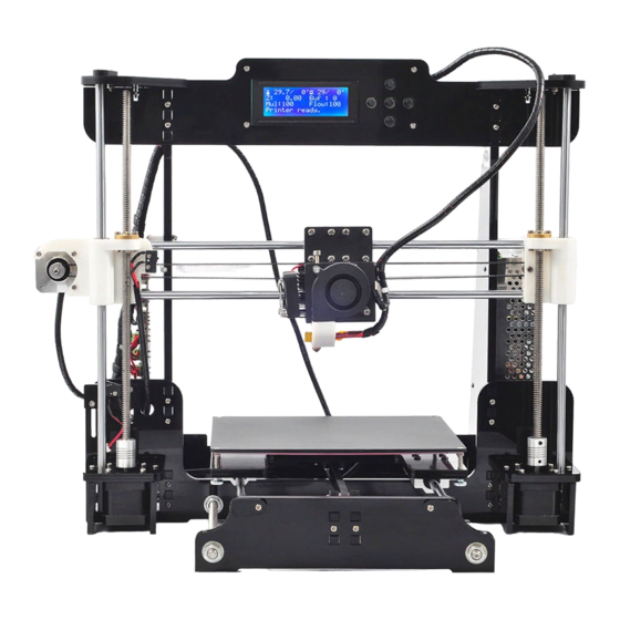
Page 40: Installation Complete
All manuals and user guides at all-guides.com Installation Complete • Congratulations ! You have just made yourself a 3D printer ! • Please contact your 3D printer supplier if any puzzles during using process. • Thank you for choosing our products, we will always provide you more services.
Need help?
Do you have a question about the M505 and is the answer not in the manual?
Questions and answers