Table of Contents
Advertisement
Quick Links
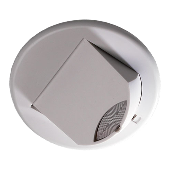
MWS3A-AT-PRM
RF ceiling microwave presence detector – Switching
Front features
Front features
Mounting Bezel
Back features
Product Guide
The MWS3A-AT-PRM is a microwave motion sensor
combined with a switched output channel.
The MWS3A-AT-PRM detects movement using a highly
sensitive microwave detector. This works by emitting low
power microwave signals and measuring the reflections as
the signals bounce off moving objects.
The output channel comprises a mains voltage relay
capable of simple on/off switching.
Functioning as a presence detector, the unit can turn lights
on when a room is occupied and off when the room is
empty. Optional settings allow lights to be turned off in
response to ambient daylight. The unit also includes stored
scenes for versatile manual on / off control of lighting.
The MWS3A-AT-PRM can be used as a standalone unit or
integrated with other devices as part of a system. The
built-in RF transceiver allows wireless communication with
all other An-10
Input Unit, useful for push-button scene selection and
absence detection.
All functionality is fully programmable.
Microwave Sensor
Detects movement within the unit's detection range,
allowing load control in response to changes in occupancy.
IR Receiver
Receives control and programming commands from an
IR (infrared) handset.
Light Level Sensor
Monitors the ambient light level, allowing load control
Sensor Lens
based on minimum and maximum Lux Level.
which covers...
Microwave Sensor
Status LEDs
IR Receiver
These flash Red and/or Green to indicate the following:
Light Level Sensor
Status LEDs
Walk Test LED active
Valid setting received
Invalid setting received
Software reset received
Factory reset received
Power Input & Switched Output Connector (Channel 1)
Used to connect mains power to the unit and to connect a
switched load.
®
compatible products, e.g. the AT-BB-IN
when movement is detected
Overview
Features
Advertisement
Table of Contents

Related Manuals for CP Electronics MWS3A-AT-PRM


Summary of Contents for CP Electronics MWS3A-AT-PRM
- Page 1 The unit also includes stored scenes for versatile manual on / off control of lighting. The MWS3A-AT-PRM can be used as a standalone unit or integrated with other devices as part of a system. The built-in RF transceiver allows wireless communication with ®...
-
Page 2: Installation
Installation Choosing a Suitable Location The MWS3A-AT-PRM is designed to be ceiling mounted and must satisfy the following criteria: Avoid positioning the unit where direct sunlight may enter the sensor element. Do not site the sensor within 1m of any lighting, forced air heating or ventilation. - Page 3 Installation The MWS3A-AT-PRM is designed to be mounted using either: Flush fixing, or Surface fixing, using the optional Surface Mounting Box (part no. MWS3A-DBB). Both methods are illustrated below. Warning - be careful bending springs when mounting unit.
-
Page 4: Wiring Examples
Wiring examples The switched output of the MWS3A-AT-PRM is used to switch a channel of standard, non-dimming luminaires. Multiple luminaires may be connected in parallel to the switched output (via the N and L/Out terminals) as long as the maximum total load is not exceeded. -
Page 5: Fault Finding
Power-up test procedure When power is applied to the unit, the load will turn on immediately. Vacate the room or remain very still and wait for the load to switch off (this should take around 10 minutes). Check that the load switches on when movement is detected. The unit is now ready for programming. -
Page 6: Basic Programming
Basic programming The functionality of the MWS3A-AT-PRM Sensor is For most basic programming operations the UHS4 handset controlled by a number of parameters which can be is recommended and the following procedures are based changed or programmed by any of the following devices: on using this device. - Page 7 Basic programming Step 1: Set channel addresses and channel load type The Sensor has one output channel: Channel 1 - Switched Output and one input channel: Channel 3 - Microwave Sensor To relate the function of different channels it is necessary to set the addresses correctly.
-
Page 8: Detection Mode
Basic programming Step 2: Set-up sensor functionality Detection Mode Switch Level On/Off The Detection Mode for the output Channel 1 can be set to Occupancy detection can be made dependant on the behave in Presence or Absence mode: ambient light level using the Lux On Level and Lux Off Level parameters. - Page 9 Basic programming Step 3: Re-program scenes The MWS3A-AT-PRM has capacity to store 20 Local Scenes Used for Occupancy Detection Scenes and 120 Area Scenes. By default all Scenes are pre-programmed with the following channel levels, but If movement is detected (in Presence mode), Local On these can be changed as required: Scene 1 is selected.
-
Page 10: Application Examples
Example 1: Offices and corridor Example 1 shows two small offices, each with four downlighters controlled by a single MWS3A-AT-PRM sensor. These are set-up for Presence detection such that the lights turn on when anyone enters the room and turn off when the room is vacated. - Page 11 Application examples Example 2: Meeting room Example 2 shows an application for a typical meeting room. An MWS3A-AT-PRM sensor is used, set-up for Absence detection. The sensor controls the six downlighters via the switched output (Channel 1). Since the detector is in Absence detection mode, lights will only turn on in response to manual operation of the button plates via the AT-BB-IN input unit or IR Handset.
-
Page 12: Advanced Programming
Advanced programming The tables on pages 12 to 14 give a summary of all programmable parameters for the MWS3A-AT-PRM Sensor. Parameter Name Default Value Range / Options Description Programming Devices UHS4 UNLCDHS For Device Product ID Automatically 1 to 999 A number used to uniquely identify each device within a range of ... - Page 13 Advanced programming Parameter Name Default Value Range / Options Description Programming Devices UHS4 UNLCDHS For Channel 3 (Microwave Sensor) Local Code 1 to 999 A number corresponding to the Local Code of all devices to be controlled by this Microwave input channel. ...
- Page 14 Advanced programming Parameter Name Default Value Range / Options Description Programming Devices UHS4 UNLCDHS When movement is detected... Local On Scene 1 to 20 The local scene request sent to all devices with the Local Code specified. ...
- Page 15 This page intentionally left blank...
-
Page 16: Technical Data
+ 44 (0) 333 900 0671 Fax: + 44 (0) 333 900 0674 www.cpelectronics.co.uk enquiry@cpelectronics.co.uk Due to our policy of continual product improvement CP Electronics reserves the right to alter the specification of this product without prior notice. Ref: #WD383 Issue 2.1...
Need help?
Do you have a question about the MWS3A-AT-PRM and is the answer not in the manual?
Questions and answers