Table of Contents
Advertisement
Quick Links
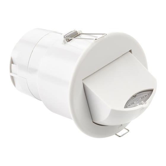
MWS3A-DD-LV
Ceiling Microwave presence detector - DALI / DSI 12-24V AC/DC
Front features
Mounting Bezel
Back features
Retaining Spring
Power Input
& Switched
Output Connector
(Channel 1)
Retaining Spring
Product Guide
The MWS3A-DD-LV microwave presence detector provides
automatic control of lighting loads with optional manual
control. It detects movement using a highly sensitive
microwave detector. This works by emitting low power
microwave signals and measuring the reflections as the
signals bounce off moving objects.
Output Channel 1 comprises a relay capable of simple on/
off switching, while Output Channel 2 provides dimmable
control of either DALI or DSI type ballasts.
Functioning as a presence detector, the unit can turn lights
on when a room is occupied and off when the room is
empty. Optional settings allow lights to be turned off in
response to ambient daylight, or to implement a maintained
illuminance (daylight harvesting) system.
The flexibility of having two channels and two switch inputs
allows the following example scenarios:
The unit has a unique adjustable sensor head that allows
the area of detection to be optimised for the application.
All functionality is fully programmable using an IR handset.
Microwave Sensor
Detects movement within the unit's detection range,
allowing load control in response to changes in occupancy.
IR Receiver
Receives control and programming commands from an
IR (infrared) handset.
Light Level Sensor
Measures the overall light level in the detection area
Status LEDs
Sensor Lens
which covers...
The LED flashes Red to indicate the following:
Microwave Sensor
Walk Test LED active
IR Receiver
Light Level Sensor
Valid setting received
Status LEDs
Power Input & Switched Output Connector (Channel 1)
Used to connect power to the unit and to connect a
switched load.
Dimmable Control Output Connector (Channel 2)
Used to connect DSI/DALI controllable ballasts and
Dimmable
transformers for dimmable loads.
Control Output
Connector
Switch Input Connector
(Channel 2)
Two input terminals can be used to manually override the
dimming levels and override the lights on or off.
Switch Input
Connector
Dim an outside row of luminaires whilst internal fittings
are switched
Provide absence detection for two separate channels
Maintained illuminance system with manual up/down
controls
Overview
Features
when movement is detected
Advertisement
Table of Contents

Related Manuals for CP Electronics Direct Dim MWS3A-DD-LV


Summary of Contents for CP Electronics Direct Dim MWS3A-DD-LV
- Page 1 Product Guide MWS3A-DD-LV Ceiling Microwave presence detector - DALI / DSI 12-24V AC/DC Overview The MWS3A-DD-LV microwave presence detector provides automatic control of lighting loads with optional manual control. It detects movement using a highly sensitive microwave detector. This works by emitting low power microwave signals and measuring the reflections as the signals bounce off moving objects.
-
Page 2: Sensor Functionality
Detection diagram Ideal for corridor or aisle applications Ideal for large office or classroom Note. If the range is compromised by the ceiling construction / material. Add the supplied 20mm spacer ring. See page 4 for fitting details. Ideal for open plan areas and offices Sensor functionality Detection Mode The Detection Mode for both output Channels 1 and 2 can be set to behave in Presence or Absence mode:... -
Page 3: Installation
Installation Choosing a Suitable Location The detector should be sited so that the occupants of the room fall inside the detection pattern shown opposite). Avoid positioning the unit where direct sunlight may enter the sensor element. Do not site the sensor within 1m of any lighting, forced air heating or ventilation. ... - Page 4 Installation The MWS3A-DD-LV is designed to be mounted using either: Flush fixing, or Surface fixing, using the optional Surface Mounting Box (part no. MWS3A-DBB). Both methods are illustrated below. Warning - be careful bending springs when mounting unit. Flush fixing Hole Ø74mm Attach cable clamp...
-
Page 5: Wiring Diagrams
Wiring diagrams Channel 1 (switched output) of the MWS3A-DD-LV Channel 2 (dimmable output) of the MWS3A-DD-LV can provides a switched low voltage output which can be used be used to control the light output of luminaires that are to power a mains load via an auxiliary relay or for other fitted with dimming ballasts/transformers. - Page 6 Two channel, individual switches Functions: Switches both channels with occupancy. Maintains illuminance, dims and switches the dimming channel using optional single position retractive switch (switch 2). Switches the switching channel using the optional single position retractive switch (switch 1). Configured to presence detection: Turns on automatically with occupancy. Maintains illuminance (dimming channel only).
-
Page 7: Fault Finding
Power-up test procedure When power is applied to the unit, the load will turn on immediately. Set the timeout to 10 seconds, vacate the room or remain very still and wait for the load to switch off . Check that the load switches on when movement is detected. The unit is now ready for programming. -
Page 8: Basic Programming
Basic programming The functionality of the MWS3A-DD-LV is controlled by a number of parameters which can be changed or programmed by any of the following devices: UHS5 Infrared Handset. See below for programmable functions. UNLCDHS Infrared Handset (with LCD). See user guide for full programming details. For most basic programming operations the UHS5 handset can be used and the following procedures are based on using this device. -
Page 9: Advanced Programming
Advanced programming UHS5 UNLCDHS Parameter Name Default Value Range / Options Description Detector Parameters When set to On this causes a red LED to flash on the sensor when it detects Walk Test LED On or Off movement. Use this feature to check for adequate sensitivity levels. Time Out 20 minutes 0-99 minutes... - Page 10 Advanced programming UHS5 UNLCDHS Parameter Name Default Value Range / Options Description Channel 1 –Switching Channel Detection Mode Presence Presence or Presence mode allows the output to turn on when movement is detected and off when movement ceases. Absence mode allows the output to turn off when Absence movement ceases, but must be manually turned on first.
- Page 11 This page intentionally left blank...
-
Page 12: Technical Data
+ 44 (0) 333 900 0671 Fax: + 44 (0) 333 900 0674 www.cpelectronics.co.uk enquiry@cpelectronics.co.uk Due to our policy of continual product improvement CP Electronics reserves the right to alter the specification of this product without prior notice. Ref: #WD612 Issue 4...
Need help?
Do you have a question about the Direct Dim MWS3A-DD-LV and is the answer not in the manual?
Questions and answers