
Subscribe to Our Youtube Channel
Related Manuals for CP Electronics MWS3A-DD


Summary of Contents for CP Electronics MWS3A-DD
-
Page 1: Table Of Contents
Product Guide MWS3A-DD Direct Dim Microwave Presence/Absence Detector Contents Section Contents Page Dimensional information Description and operation Wiring & Fixing Installation Fixing - Flush Fixing - Surface Head locking Time, Lux & Sensitivity adjusters Programming Wiring diagrams Detection pattern diagrams... -
Page 2: Description And Operation
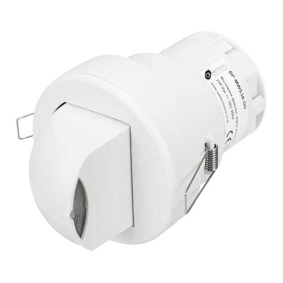
It can be used on incandescent, fluorescent and compact fluorescent lighting and DSI or DALI digital dimming ballasts over 1 or 2 channels. The MWS3A-DD detects movement using a highly sensitive microwave detector. This works by emitting low power microwave signals and measuring the reflections as the signals bounce off moving objects. -
Page 3: Wiring & Fixing
3. Wiring & Fixing Wire the products using the diagrams shown in section 10. To switch from more than one position simply wire two or more units in parallel using the Live, Neutral, Switched Live and manual switch wires only. The dimming connection must be wired to one unit only. -
Page 4: Fixing - Flush
5. Fixing - Flush Warning - be careful bending springs when mounting unit. Hole Ø74mm Attach cable clamp. 6. Fixing - Surface Warning - be careful bending springs when mounting unit. Hole Ø30mm MAX 50mm or 60mm fixing centres page 4... -
Page 5: Head Locking
7. Head Locking Adjust head to required position. Remove metal locking clip from rear of unit. Push clip into position shown below to lock head. To remove clip, lever out with a small screwdriver. 8. Time, Lux & Sensitivity Adjusters ... -
Page 6: Programming
Switching Channel 1 functions (factory default in brackets): 3.1 Presence detection Auto switch on with detection, auto off after movement ceases (MWS3A-DD default) and time delay ends. 3.2 Absence detection Manual switch on, auto off after movement ceases and time (MWS3A-DD/ABS default) delay ends. - Page 7 Dimming Channel 2 functions (factory default in brackets): Light level Maintained illuminance level (adjustable between 1 and 999). At 999 the output will be always be at maximum. Presence detection Auto switch on with detection, auto off after movement ceases and (default) time delay ends.
-
Page 8: Wiring Diagrams
EBDSPIR-DD SENSOR MWS3A-DD SENSOR When there is a requirement to have an ‗Off‘ state that requires a permanent dimmed level. Then use the DSI / DALI ―pair‖ to both switch and dim, and a live feed direct to the ballast. Set the ‗Off value‘ (section 4.10 in the Programming section) to a value greater than zero to achieve a permanent dimmed level for... - Page 9 (240V SWITCHING) Optional for presence, EBDSPIR-DD SENSOR mandatory for absence detection MWS3A-DD SENSOR 10.3 Two channel, common switch Functions: Switches both channels with occupancy. Maintains illuminance, dims and switches the dimming channel using optional centre biased retractive switch . Configured to presence detection: Turns on automatically with occupancy. Maintains illuminance (dimming channel only).
- Page 10 RETRACTIVE SWITCH (240V SWITCHING) Optional for presence, mandatory for absence detection EBDSPIR-DD SENSOR MWS3A-DD SENSOR PLEASE NOTE THAT THE CENTRE BIASED RETRACTIVE SWITCH WILL PROVIDE CONTROL FOR THE DIMMING LUMAIRE(S) ONLY. THE NON-DIMMING LUMINAIRE(S) WILL BE CONTROLLED ONLY BY THE SENSOR 10.4 Single channel switching...
-
Page 11: Detection Pattern Diagrams
11. Detection Patterns Ideal for large office or classroom Ideal for corridor or aisle applications Ideal for open plan areas and offices 12. Fault Finding LOAD DOES NOT COME ON LIGHTS DO NOT GO OFF Check to see if the live supply to the circuit is Ensure that the area is left unoccupied for a good. -
Page 12: Specification
+ 44 (0) 333 900 0674 www.cpelectronics.co.uk FM 45789 EMS 534520 enquiry@cpelectronics.co.uk Due to our policy of continual product improvement CP Electronics reserves the right to alter the specification of this product without prior notice. Ref #WD288 Issue 3 page 12...
Need help?
Do you have a question about the MWS3A-DD and is the answer not in the manual?
Questions and answers