Table of Contents

Related Manuals for HF Scientific Micro TOL


Summary of Contents for HF Scientific Micro TOL
- Page 1 OWNERS MANUAL Micro TOL 0-1000 NTU HF scientific, inc. 3170 Metro Parkway Ft. Myers, FL 33916 Phone: 239-337-2116 Fax: 239-332-7643 E-Mail: info@hfscientific.com Website: www.hfscientific.com Catalog No. 24031 (12/04) Rev. 2.7...
- Page 3 Type of Equipment: Process Turbidimeter Model No: Micro TOL I, the undersigned, hereby declare that the equipment specified above conforms to the above Directive and Standard Place: Fort Myers, Florida USA (Signature) Robert J. Maley, President MICRO TOL (12/04) REV. 2.7...
- Page 4 MICRO TOL (12/04) REV. 2.7...
-
Page 5: Table Of Contents
Configuring the RS-485 I/O Port (if equipped) ........22 Setting the Security Access..............25 Saving Configuration Settings .............25 Troubleshooting & Maintenance ..............26 Micro TOL Fault Detection ..............26 System Fail Message ................26 Diagnostic Chart .................27 Technical and Customer Assistance ...........27 MICRO TOL (12/04) - Page 6 Routine Maintenance ..................28 Cleaning the Flow Through Cuvette ...........28 Replacing or Installing the Desiccant Pouch ........28 Replacing the Source Lamp ..............29 Replacing the Battery ................29 10.0 Accessories and Replacement Parts List ............29 11.0 Warranty ......................30 MICRO TOL (12/04) REV. 2.7...
-
Page 7: Specifications
IP 66 /NEMA 4X Regulatory Compliance (20023) White Light Version compliant to U.S. EPA 180.1 (0-10NTU) (20024) Infrared Version compliant to ISO 7027 Shipping Weight 2.5 kg (5.5 lbs.) Warranty 1 Year from date of shipment MICRO TOL (12/04) Rev. 2.7... -
Page 8: Overview
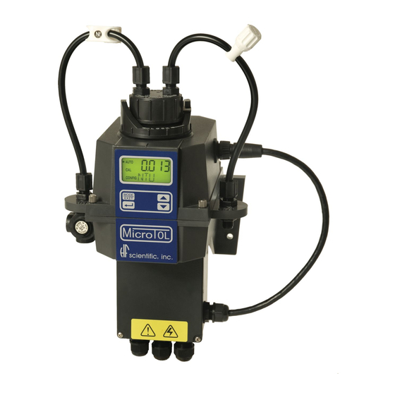
The MICRO TOL process turbidimeter allows you to measure the turbidity of your process water on-line. The White Light MICRO TOL has been designed to meet the design criteria specified by the US EPA on turbidity measurement. The infrared MICRO TOL was designed to meet the design criteria specified in ISO 7027 and DIN 27027 for the measurement of the turbidity of a sample. -
Page 9: The Touch Pad
All items used on the display are shown in this figure 1.3 The Touch Pad Figure 2: The Micro TOL touch pad. Figure 2 illustrates the touch pad. The touch pad has four buttons: MODE/EXIT, ↵, t, and u. The MODE/EXIT button is used to cycle between the four operational modes of the instrument: CAL, CAL OFFSET, CONFIG, and AUTO (Measurement) mode. -
Page 10: Vapor Purge
1.4 Vapor purge The Micro TOL is equipped with a continuous vapor purge system. A replaceable desiccant pouch in the lower portion of the instrument dries the air. System heat is used to warm the air. A fan inside the instrument continuously circulates heated dry air around the optical well and the flow through cuvette. -
Page 11: Safety
In certain instances Notes, or helpful hints, have been highlighted to give further clarification to the instructions. Refer to the Table of Contents to easily find specific topics and to learn about unfamiliar terms. MICRO TOL (12/04) Rev. 2.7... -
Page 12: Installation And Commissioning
M6 (¼”) for the instrument enclosure and M4 (3/16”) for the junction box. The Micro TOL is designed to have the field terminal box cradled under the sensor portion of the instrument. It is recommended that the field terminal box be mounted first, and then the rest of the instrument be mounted on top. -
Page 13: Plumbing
Note: The foot valve system can handle up to 1.5 liters per minute (0.4 gallon per minute). Flow rates higher than this will cause the instrument to flood in the event of a ruptured cuvette. MICRO TOL (12/04) Rev. 2.7... -
Page 14: Pressurized Systems
PSI) or 7.62 m (25 foot) of head or limit the flow the 1 liter per minute. An inline flow regulator is available from HF scientific inc. catalog number 19778. 3.2.2 Drain Vent: The Micro TOL has been fitted with a drain vent in the “OUT” bulkhead fitting. This fitting allows for atmospheric equalization, thus helping to alleviate bubble formation in the cuvette. -
Page 15: Power
While making your connections, refer to Figure 5. The Micro TOL is not supplied with a power cord. Note: Your Micro TOL is equipped standard with a 4-20 mA output and alarm relays. If the optional RS-485 is installed, the 4-20 mA and the relays are disabled and you should ignore all references to these items. -
Page 16: Operation
If the dashes remain for an extended period of time, please remove the flow through cell and check the sample for a large amount of bubbles present. If the problem persists, please contact the HF scientific, inc. Technical Services Department for further assistance and guidance. -
Page 17: Security Access Feature
If you have selected the valid access code, the instrument will be directed to the calibration mode. If the wrong access code is selected, the instrument will return to the AUTO mode. Refer to section 7.7 Setting the Security Access for more information. MICRO TOL (12/04) Rev. 2.7... -
Page 18: Instrument Calibration
AUTO mode after a thirty (30) minute period of inactivity. 5.1 Calibration Standards If the Micro TOL will be used over the entire range of .02 to 1000 NTU a complete calibration as described below will be required. If instrument accuracy is only required below 10 NTU, such as potable water, a calibration may be performed using only a 10 NTU and a 0.02 NTU standard. - Page 19 15. The instrument will show alternating END and ↵. 16. Press the ↵ button to accept the calibration. 17. The instrument will display SAVE on the lower display briefly and then the Mode will return to AUTO. MICRO TOL (12/04) Rev. 2.7...
- Page 20 It is recommended that the measurement chamber be kept covered during the calibration period and that the flow through cuvette be replaced immediately after the calibration to prevent premature contamination of the desiccant. MICRO TOL (12/04) Rev. 2.7...
-
Page 21: Instrument Offset
NTU value. As an example if the Micro TOL measures the process at 0.16 NTU but the laboratory instrument read the sample at 0.12 NTU, adding an offset of –0.04 would result in the Micro TOL displaying 0.12 NTU. -
Page 22: Indexing Calibration Cuvettes
Now push and release the ↵ then thetbutton. Factory calibration and factory configuration have now been restored. Note: Restoring the factory settings allows the use of the Micro TOL with reduced accuracy. The original problem still exists and must be determined and corrected before accurate operation of the Micro TOL will be resumed. -
Page 23: Instrument Configuration (Config Mode)
7.2 Setting the Year With the YEAR showing and the year displayed, change the displayed year using the t or u buttons. When you have selected the proper year press the ↵ button to accept the year. MICRO TOL (12/04) Rev. 2.7... -
Page 24: Setting The Day And Month
↵ button. 7.4 Setting the Time After pressing the ↵ button, HOUR will be displayed and you will see the time displayed on the LCD screen in 24-hour format corresponding to the hour. MICRO TOL (12/04) Rev. 2.7... -
Page 25: Programming The Alarms & 4-20 Ma (If Used)
If the delay on time is set at 5 seconds and the process turbidity exceeds the set point continuously for only 4 seconds, the alarm will not be activated. However, process turbidity exceeds the set point continuously for 5 seconds or more, the instrument will activate the alarm. MICRO TOL (12/04) Rev. 2.7... -
Page 26: Alarm 1
Once you have set the desired delay time, press the ↵ button to accept it. Delay Off: Next, the following display will appear to allow you to select the number of seconds currently set for the “delay off” time. MICRO TOL (12/04) Rev. 2.7... -
Page 27: Alarm 2
Once you have set the desired level, press the ↵ button to accept it. Next, you will be prompted with the turbidity level assigned to the 20 mA output level (UPLM on the lower row of the LCD display). MICRO TOL (12/04) Rev. 2.7... -
Page 28: Configuring The Rs-485 I/O Port (If Equipped)
HOUR, 8 HOUR, 15 MIN & 30 MIN. Use thet or u button to change and the ↵ button to select. You will then be requested to select the BAUD. Note: The timing for the interval starts at midnight. MICRO TOL (12/04) Rev. 2.7... - Page 29 RS-485. If the timed print option was turned OFF, the next prompt will be for the address of the Micro TOL. Here you can select the desired instrument address (1-255) using the t or u buttons.
- Page 30 An optional PC software package, called HF ONLINE (HF catalog # 19783) allows for an interface with up to 255 Micro TOL’s for the purpose of data logging. This package is similar to a small SCADA system and operates by communicating over the interface.
-
Page 31: Setting The Security Access
You will now see a screen with the word SAVE on the lower row of the display, indicating that your settings were saved. The Micro TOL will automatically return to the normal AUTO mode of the instrument. -
Page 32: Troubleshooting & Maintenance
Troubleshooting & Maintenance 8.1 Micro TOL Fault Detection The Micro TOL performs continuous diagnostic monitoring. In the Micro TOL there are three levels of fault detection; warnings, errors and failures. A warning indicates that there is a system problem that does not interfere with the operation of the instrument and can be corrected by the operator. -
Page 33: Diagnostic Chart
8.4 Technical and Customer Assistance If for any reason you need assistance regarding this instrument please do not hesitate to contact either the HF scientific, inc. Technical Service Department or the HF scientific, inc. Customer Service Department: HF scientific, inc. -
Page 34: Routine Maintenance
9.2 Replacing or Installing the Desiccant Pouch The Micro TOL continuously checks the condition of the desiccant tray. When the desiccant gets in such a condition that it may cause problems, the instrument will display DESC on the lower portion of the display. -
Page 35: Replacing The Source Lamp
9.3 Replacing the Source Lamp The source lamps in the Micro TOL’s are designed for long life. The IR lamp is rated for 10 years and the white light version is rated for 7 years. If your lamp should need replacement, we recommend you call HF Customer Service Department for assistance. -
Page 36: Warranty
11.0 Warranty HF scientific, inc., as vendor, warrants to the original purchaser of this instrument that it will be free of defects in material and workmanship, in normal use and service, for a period of one year from date of delivery to the original purchaser. HF scientific, inc.’s, obligation under this warranty is limited to replacing, at its factory, the instrument or any part thereof.
Need help?
Do you have a question about the Micro TOL and is the answer not in the manual?
Questions and answers