Table of Contents
Advertisement
Advertisement
Table of Contents

Subscribe to Our Youtube Channel
Related Manuals for HF Scientific CLX


Summary of Contents for HF Scientific CLX
- Page 1 OWNER’S MANUAL CLX OnLine Residual Chlorine Monitor HF scientific 3170 Old Metro Parkway Ft. Myers, FL 33916 Phone: 239-337-2116 Fax: 239-332-7643 Toll Free: 888-203-7248 Email: HF.Info@Wattswater.com Website: www.hfscientific.com Catalog #24420 (4/18) REV 6.0...
-
Page 3: Declaration Of Conformity
Conforms to: UL 61010-1 Issued May 11, 2012 Ed 3 and CAN/CSA-C22.2# 61010-1 Issued May 11, 2012 Emissions & Immunity – Tested and passed: EN61326-1: 2013 Manufacturer’s Name: HF scientific, inc. Manufacturer’s Address: 3170 Old Metro Parkway, Fort Myers, Florida 33916-7597 Importer’s Name: Importer’s Address:... - Page 4 Catalog #24420 (4/18) REV 6.0...
-
Page 5: Table Of Contents
Table of Contents Section Page Specifications ....................1 Overview ......................2 Unpacking and Inspection of the Instrument and Accessories .....2 The Display ...................3 The Touch Pad ..................3 Safety .........................4 Symbols Used In This Manual ...............4 Theory of Operation ..................5 Installation and Commissioning ..............6 Mounting &... -
Page 6: Section Page
8.2.1 HF Online Communication ............22 8.2.2 Simple Communication ............22 8.2.3 Modbus Communication ............23 Remote Panel Meter ................23 Desiccant Cartridge ................23 Troubleshooting .....................24 CLX Fault Detection ................24 Setting Flow Rate .................25 Clearing Faults ..................25 Reagent Clogs ..................25 Diagnostic Chart .................26 Technical and Customer Assistance ...........26 10.0... -
Page 7: Specifications
EMC to EN61326-1: 2013 Shipping Weight 3.9 kg (8.6 lbs.) Reagents Shipped Separately 406 mm X 406 mm X 241 mm (16”X 16” X 9 ½”) Shipping Dimensions 2 Years from date of manufacture Warranty CLX (4/18) Page 1 REV 6.0... -
Page 8: Overview
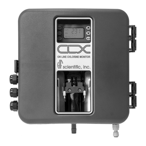
Overview The CLX Online Chlorine Analyzer allows for the reading of chlorine levels of process water on-line. The CLX has been designed to meet the design criteria specified by Standard Methods for the Examination of Water and Wastewater (22 Edition) Method 4500-Cl G. -
Page 9: The Display
SERVICE button will drain the instrument and hold all operations until either the SERVICE button is pushed again or the power is reset. This button should be used while changing the tubing, the measurement cuvette or reagent bottles. Figure 2: The CLX touch pad. CLX (4/18) Page 3... -
Page 10: Safety
This symbol identifies important information, practices or actions. This pictorial alert you to the need read the manual, possibly at a different section. This pictorial alerts electricity, electrocution and shock hazards. CLX (4/18) Page 4 REV 6.0... -
Page 11: Theory Of Operation
Theory of Operation The CLX has two solenoid valves, one for sample water (FLOW) and one for draining of the cuvette (PURGE). A third solenoid, along with four check valves forms a reagent pump. Sample water flow is controlled by the FLOW solenoid valve. The PURGE solenoid valve is used to empty the cuvette in the measurement chamber. -
Page 12: Installation And Commissioning
(within 2-3 meters (6-10 ft) of the sampling point). The provided mounting feet will need to be installed with the provided screws. These can be rotated as shown above. Suggested mounting screws are up to M6 (¼”). CLX (4/18) Page 6 REV 6.0... -
Page 13: Plumbing
The drain tubing connects to a hose barb. The rated tubing size is ½” ID tubing. It is recommended that opaque tubing be used to prevent algae growth. Keep this tubing as short as possible. This drain must be kept open to the atmosphere. CLX (4/18) Page 7 REV 6.0... -
Page 14: Electrical Connections
The fluid waste from drain connection of this instrument contains reagents diluted with large quantities of sample water. HF scientific recommends that operators check with local authorities concerning proper disposal of waste fluids. This waste fluid must NEVER be reintroduced into the incoming water stream. -
Page 15: Power
(Catalog No. 20779S). The CLX is not supplied with a power cord. If the CLX is to be used in the U.S. or Canada the power cord must be UL Listed & CSA Certified. Please consult all local electrical codes for proper connection. -
Page 16: Relays
The 4-20 mA output is driven by a 15 VDC power source and can drive recorder loads up to 600 ohms. Transformer isolation is provided on the CLX. Do not run 4- 20 mA cables in the same conduit as power. Operation of this output is covered in section 7.1 Setting the 4-20 mA. -
Page 17: Operation
Operation The CLX Online Chlorine Analyzer allows for the measurement of the chlorine of process water on-line. The chlorine value of the process water is usually reported in milligrams per Liter (mg/L), these units are equivalent to Parts Per Million (PPM). -
Page 18: Security Access Feature
This normal operation for the instrument and does not represent an error or problem. The white LED is also used to draw attention to a problem as described in section 9.0 CLX Fault Detection. In these instances the white LED blinks at a constant rate dependant on the severity of the problem, but is still turned off as described above. -
Page 19: Instrument Calibration
3. On the CLX, press the MODE/EXIT button once. The screen is shown below. 4. Press to enter the calibration adjustment. 5. The screen will show the current reading on the CLX. Using the & buttons adjust the reading to agree with the laboratory method or portable photometer. -
Page 20: Zero (Offset) Calibration Procedure
SERVICE mode to clear this error. 6.3 Restore Factory Settings If the CLX displays a CAL error or the calibration was incorrectly performed, it may be desired to restore the factory calibration. All factory defaults including factory configurations can be reset by holding down the button and then pressing and releasing the ... -
Page 21: Instrument Configuration (Config Mode)
Once the desired level has been set, press the button to accept it. The 4MA can be set higher than 20MA level to invert the output current if required. This may be required to control a dosing pump. CLX (4/18) Page 15 REV 6.0... -
Page 22: Configuring The Error Level
7.2 Configuring the Error Level In case of an error in the CLX, the 4-20 mA reading can be used to indicate a problem by sending the current to either 4.00 mA, 2.00 mA or 0 mA. The factory default setting is OFF. -
Page 23: Configuring The Alarms
OFF, the next selection for the speed of response RESP is shown. Due to the cyclic nature of the CLX, relay chatter is not an issue. There is no need for alarm delays or hysteresis. -
Page 24: Enabling The Security Access
If extended settings are set to OFF, pressing the button will save all settings and the CLX will automatically return to the normal AUTO mode of the instrument. 7.7 Units of Measurement The unit of measure can be set to either mg/L (milligrams per liter) or PPM (parts per million). -
Page 25: Averaging And Filtering
7.8 Averaging and Filtering The CLX can display and output averaged readings to help smooth out the response and eliminate large reading variation in rapidly changing processes. There are 5 settings for the averaging feature: 1 = No averaging, each reading is in “real time”. -
Page 26: Rs-485 Parameters
Make selections using the and buttons then press the button to exit to AUTO mode and save all configuration settings. If the 4-20 mA in section 7.1 is turned ON, there are two additional menus that will appear before returning to AUTO mode. CLX (4/18) Page 20 REV 6.0... -
Page 27: Ma Adjustment
The adjustment can be made using the and buttons. This adjustment will allow the operator to make the CLX agree with a PLC or SCADA system. The adjustment limits are ± 200 counts or about ± 0.2 mA. -
Page 28: Additional Features And Options
CONFIG mode. 8.2 RS-485 Outputs The CLX has the capability to operate in three different RS-485 modes. Included is a mode for interfacing into the HF Online software package (section 8.2.1 below), a simple communication mode and Modbus communications. -
Page 29: Modbus Communication
8.3 Remote Panel Meter (Catalog # 19609) The remote panel meter allows for remote indication of the mg/L reading using the 4-20 mA loop of the CLX. No external power is required, as the meter is run off of the 4-20 mA source of the CLX. -
Page 30: Troubleshooting
Troubleshooting 9.1 CLX Fault Detection The CLX performs continuous diagnostic monitoring. In the CLX, there are 4 severity levels of fault detection. Level 4, 3 & 2 will allow normal operation, but warn of the problem. Level 1 is an instrument failure and the instrument will not operate. Any faults are displayed in a queue form in the bottom row of the LCD. -
Page 31: Setting Flow Rate
3. Display will show FLOW with the number 0. Press either the or button. 4. CLX will drain, and then pulse in water while a count is displayed on the screen. 5. The display will show one of three messages HI, LO or Good. -
Page 32: Diagnostic Chart
9.6 Technical and Customer Assistance If for any reason assistance is needed regarding this instrument please do not hesitate to contact either the HF scientific Technical Service Department or the HF scientific Customer Service Department: HF scientific 3170 Old Metro Parkway... -
Page 33: Routine Maintenance
Cap Assemblies Pump Tubes Cuvette Two complete cap assembly sets are used in the CLX; one for the buffer and one for the indicator. The supplied kit is intended to last for one year. Additional kits can be ordered from your local HF scientific distributor or representative. - Page 34 PRIME and then one time to restart reagent flow. The system will automatically return to normal operation. Tubes may darken due to contact with the reagent. This condition does not affect the performance of these parts. CLX (4/18) Page 28 REV 6.0...
-
Page 35: Preventative Maintenance Schedule
Once per year Check Valve Kit Cat # 25017S Clean T-Strainer Screen Once per year Clean or replace if needed Cat #28625S Follow the enclosed procedures with any of the kits or parts mentioned above. CLX (4/18) Page 29 REV 6.0... -
Page 36: Replacing Or Installing The Reagents
Remove the cap on both bottles replace with the cap supplied with the CLX. Be sure to replace the reagents in the correct location as labeled on the inside of the CLX. The buffer is installed on the left and the indicator is installed on the right side. The suction tube for both reagents will reach the bottom of the bottles. -
Page 37: Check Valve Flushing Kit
Figure 7: Check Valve Flushing Kit 10.5 Instrument Storage If the CLX is relocated or will be inactive for more than 48 hours, remove the reagents. Flush the reagent system as describe in 10.1 Maintenance Schedule. Place the instrument in Service mode to drain the system then remove power by disconnecting the mains power plug. -
Page 38: Accessories And Replacement Parts List
J.A.W. Reagent Kit – Free Chlorine 12 month supply 09955 12 kits of 09951 J.A.W. Reagent Kit – Total Chlorine 12 month supply 09956 12 kits of 09952 Operating Manual CLX 24420 Tubing/Cuvette Kit 09950 Replacement T-Strainer Screen 28625 CLX (4/18) Page 32 REV 6.0... - Page 39 Check Valve Flushing Kit 25096 To order any accessory or replacement part, please contact the HF scientific Customer Service Department. If for any reason technical assistance is needed regarding this instrument, please do not hesitate to contact the HF scientific Technical Services Department.
-
Page 40: Warranty
12.0 Warranty HF scientific inc., as vendor, warrants to the original purchaser of this instrument that it will be free of defects in material and workmanship, in normal use and service, for a period of two years from date of manufacture. This warranty includes only instruments coved in this manual manufactured after January 1, 2012.
Need help?
Do you have a question about the CLX and is the answer not in the manual?
Questions and answers