
Related Manuals for HF Scientific Micro TOL2 WL


Summary of Contents for HF Scientific Micro TOL2 WL
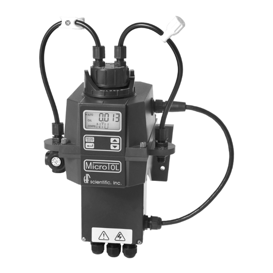
- Page 1 OWNER’S MANUAL MicroTOL Series Turbidimeter HF scientific 3170 Metro Parkway Ft. Myers, FL 33916 Phone: 239-337-2116 Fax: 239-332-7643 E-Mail: hfinfo@watts.com Catalog No. 24034 (8/07) Rev. 4.1 Website: www.hfscientific.com...
-
Page 3: Declaration Of Conformity
24, 2003 - Tested and passed ETLc (tested to CSA C22.2#1010.1-92) Emissions & Immunity – Tested and passed EN61326: 1997 + A1:1998 + A2:2001 + A3:2003 Manufacturer’s Name: HF scientific Manufacturer’s Address: 3170 Metro Parkway, Fort Myers, Florida 33916-7597 Importer’s Name: Importer’s Address:... -
Page 5: Table Of Contents
Table of Contents Section Page Specifications ....................1 Overview ......................2 The Micro TOL Series ................. 2 Unpacking and Inspection of the Instrument and Accessories ..... 3 The Display ..................3 The Touch Pad ..................4 Vapor Purge................... 4 Safety......................... 4 Installation and Commissioning ............... - Page 6 Table of Contents (continued) Section Page Enabling the Security Access .............. 20 Extended Settings ................20 Speed of Response................20 Displayed Resolution ................. 21 7.10 LCD Backlight Brightness ..............21 7.11 Setting the Units .................. 22 7.12 Ultrasonic Cleaning................22 7.13 RS- 485 Parameters ................
-
Page 7: Specifications
Specifications Measurement Range 0 – 1000.0 NTU 0 – 100 NTU (Model 20055 & 20056) Accuracy ±2% of reading or ±0.02 NTU below 40 NTU whichever is greater ±5% of reading above 40 NTU Resolution 0.0001 NTU (below 10 NTU) Response Time Adjustable Multi-Line Liquid Crystal Backlit Display... -
Page 8: Overview
The Micro TOL series instruments have a wide variety of options available. Refer to the table below to determine which factory installed options are available. Catalog Description RS-485 Modbus Backlight Ultrasonic Range Flow Cleaning Alarm 20053 Micro TOL2 WL Standard Standard Standard 0-1000 Option 20054 Micro TOL2 IR Standard Standard Standard 0-1000 Option... -
Page 9: Unpacking And Inspection Of The Instrument And Accessories
Remove the instrument from the packing carton. Carefully inspect all items to ensure that no visible damage has occurred during shipment. If the items received do not match the order, please immediately contact the local distributor or the HF scientific, inc. Customer Service department. -
Page 10: The Touch Pad
LCD display will show DESC on the lower line in the event that the desiccant pouch needs replacement. Replacement desiccant pouches are available from HF scientific, inc. or the local representative (Part # 21555R). Refer to section 10.2 Replacing or installing the Desiccant Pouch. -
Page 11: Installation And Commissioning
Installation and Commissioning Prior to use for the first time, the supplied desiccant pouch will need to be installed. Refer to section 10.2 Replacing or Installing the Desiccant Pouch. 3.1 Mounting & Site Selection The instrument is designed for wall mounting. If wall mounting is not practical, the instrument can be mounted on any suitable level surface. -
Page 12: Plumbing
3.2 Plumbing The recommended plumbing for the instrument is shown in Figure 4. The instrument is designed to require very little head pressure to operate; around 6.9kPa (1 PSI). The flow through cuvette is rated for a flow of 100ml/min. – 1 liter/min. (0.026-0.26Gal/min). The integral pressure regulator is rated for a maximum pressure of 1380 kPa (200 PSI.). -
Page 13: Drain Vent
The sensor drain tubing should be routed to a suitable drain. It is not recommended to reintroduce the drain sample to the process stream. 3.2.2 Wetted Materials: HF scientific inc. accepts no responsibility for damage caused by the introduction of vapors, fluids or other materials into the instrument process stream which is not compatible with the instrument’s wetted materials. -
Page 14: Power
Figure 5: Electrical Connections for the Instrument 3.3.1 Power: The instrument is equipped with a 100-240 VAC, 47-63 Hz switching power supply; please verify that the line voltage falls within these specifications. It is recommended that a circuit breaker be placed prior to the power connection to allow for service. -
Page 15: Operation
Operation This process turbidimeter allows for the measurement of the turbidity of process water on- line. The turbidity of the process water is usually reported in Nephelometric Turbidity Units (NTU), but may be reported in Formazin Nephelometric Units (FNU). Readings above 1000 NTU (100 for models 20055 &... - Page 16 The security code (333) must be entered to gain access to CAL or CONFIG menus. Notice that the first number in the code is flashing; the flashing indicates that this is the number to be changed. Use the t u arrows to select the first of the three numbers in the code and then press the ↵...
-
Page 17: Instrument Calibration
Formazin is used to achieve the accuracy quoted for the instrument. A Formazin Stock Solution Kit is available from HF scientific, inc. (Catalog No. 50040). The HF scientific, inc. , primary calibration standards (refer to section 11.0 Accessories and Replacement Parts List) are more stable... -
Page 18: Calibration Procedures
5.2 Calibration Procedures 1. Select the calibration function of the instrument by pressing the MODE/EXIT button once. The arrow beside CAL will be illuminated on the display. The lower display shows alternating 1000 (the value of the standard that is requested) and ↵. The upper display shows the real-time reading to allow the standard to be indexed. -
Page 19: Calibration Error
12. Insert the requested 0.02 NTU standard. Index the standard to the lowest value on the upper display. 13. Press the ↵ button to accept the calibration. 14. The lower display will count down the progress of the calibration step. 15. -
Page 20: Instrument Offset
2. Take the grab sample and measure its turbidity using a laboratory turbidimeter (contact the HF scientific, inc. customer services department for examples of laboratory turbidimeters). 3. Compare the turbidity reported by the instrument to that obtained in the laboratory. If the readings are very close, then no offset adjustment or calibration is required and the procedure may be stopped at this step. -
Page 21: Indexing Calibration Cuvettes
To achieve the greatest accuracy, and account for normal scratches and aberrations in cuvette glass when calibrating, HF scientific inc. recommends indexing the cuvettes. Standards and standard kits purchased from HF scientific are supplied with indexing rings. The following steps allow repeatable indexing of calibration standards: 1. -
Page 22: Instrument Configuration (Config Mode)
Instrument Configuration (CONFIG mode) The instrument has been designed to provide the ability to customize the instrument according to needs at any time during normal operation. This mode has been split into sub-menus to facilitate instrument configuration. This section describes how to use each of the sub-menus to configure the instrument. -
Page 23: Configuring The Rs-485 Port
Once the desired level has been set, press the ↵ button to accept it. The next, prompt will be the turbidity level assigned to the 20 mA output level (UPLM on the lower row of the LCD display). Select the turbidity level to assign to the UPLM using the t and u buttons. -
Page 24: Configuring The Alarms
7.4 Configuring the Alarms Two relays are provided that are designed to operate as two independent programmable alarms. Three types of information must be input to fully program each alarm: 1. The alarm function (HI, LO, or OFF) 2. The alarm set point (level at which the alarm activates) 3. -
Page 25: Alarm 2
Alarm 1 Set Point: This prompt is used to select the set point for this alarm; this is indicated by “S/P” shown on the lower row of the display. Select the desired alarm level by using the t and u buttons. Once the desired set point has been set, press the ↵ button to accept it. -
Page 26: Enabling The Security Access
7.6 Enabling the Security Access The instrument is equipped with a security access. If this option is turned on, the user is required to input the access code into the instrument to get to any mode other than AUTO. The only code is 333. This code may not be changed. See section 4.2 for more information on this security feature. -
Page 27: Displayed Resolution
7.9 Displayed Resolution The instrument is equipped with the ability to display several levels of resolution. The instrument can display up to four digits to the right of the decimal place for turbidity readings below 10 NTU. The default setting is 0.01 NTU. If the last digit or two is not stable, adjust the resolution to hide these digits. -
Page 28: Setting The Units
7.11 Setting the Units The most common unit is NTU (Nephelometric Turbidity Units) however the instrument can display in FNU (Formazin Nephelometric Units). All instruments are shipped from the factory set in NTU mode. Make a selection using the t and u buttons then press the ↵... -
Page 29: Desiccant Alarm
7.14 Desiccant Alarm When the humidity detector in the Micro TOL indicates that the internal environment is close to the point where humidity could cause condensation, the instrument will display DESC as a warning. If desired, a desiccant warning can activate the alarms and send the 4-20mA to 2mA. -
Page 30: Additional Features And Options
Additional Features and Options 8.1 Backlit LCD The backlit LCD allows for easier readability of the LCD display in low light or no light conditions. The backlight is intended for continuous operation. The brightness is adjustable from a menu in the CONFIG mode. 8.2 Ultrasonic Cleaning (Models 20055, 20056, 20063 &... -
Page 31: Rs-485 Output
SENSOR (TOP VIEW) ULTRASONIC SPRING FLOW THROUGH CONNECTIONS CUVETTE ULTRASONIC TRANSDUCER Figure 6: Operational parts of the Ultrasonic Cleaning System 8.3 RS-485 Outputs The Micro TOL has the capability to operate in three different RS-485 modes for all models. Included is a mode for interfacing into the HF Online software package (section 8.3.1 below), and a simple communication mode. -
Page 32: Modbus Communication
• The same attention character “:” in ASCII or 3A Hex • The address of the Micro TOL • The Reading • The Unit (NTU) A sample communication would look like this: (Master computer requesting a report from address #1) : 1 CRLF (Micro TOL set to address #1 Response) :001 0.0249 NTU... -
Page 33: Troubleshooting & Maintenance
9.2 System FAIL Message Normally, this condition indicates that the instrument will require servicing. Contact either the HF scientific, inc. Technical Service Department or the HF scientific, inc. Customer Service Department. HF scientific 3170 Metro Parkway... -
Page 34: Diagnostic Chart
9.4 Technical and Customer Assistance If for any reason assistance is needed regarding this instrument please do not hesitate to contact either the HF scientific, inc. Technical Service Department or the HF scientific, inc. Customer Service Department: HF scientific... -
Page 35: Routine Maintenance
The desiccant should be replaced when the instrument displays DESC . A new sealed desiccant pouch and indicator card are available from HF scientific inc. part #21555R .To initially install or remove the old desiccant, simply unscrew the four corner thumbscrews and remove the electronics half of the instrument. -
Page 36: Accessories And Replacement Parts List
1-shutoff clamp, 1-backpressure valve, 2-connecting tubing with fittings for flow through assembly, drain vent. To order any accessory or replacement part, please contact the HF scientific Customer Service Department. If for any reason technical assistance is needed regarding this instrument please do not hesitate to contact the HF Technical Services Department. -
Page 37: Warranty
12.0 Warranty HF scientific, inc., as vendor, warrants to the original purchaser of this instrument that it will be free of defects in material and workmanship, in normal use and service, for a period of one year from date of delivery to the original purchaser. HF scientific, inc.’s, obligation under this warranty is limited to replacing, at its factory, the instrument or any part thereof.
Need help?
Do you have a question about the Micro TOL2 WL and is the answer not in the manual?
Questions and answers