Table of Contents
Advertisement
Quick Links
Biopel
MINI
User Manual
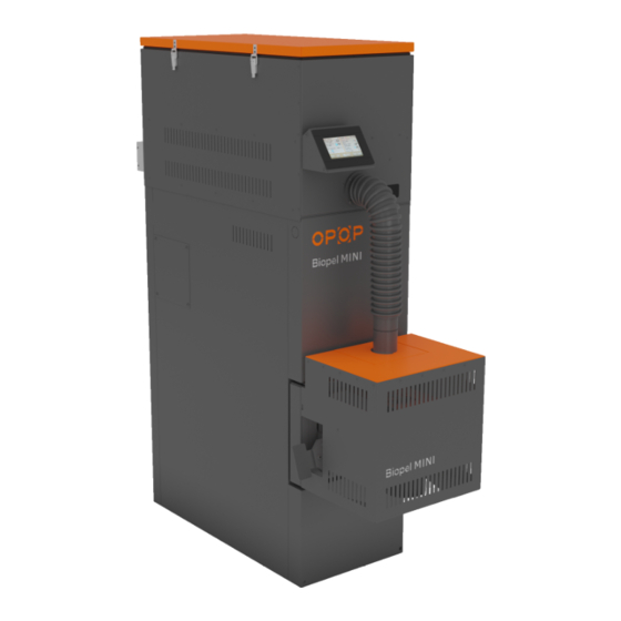
Biopel MINI series pellet boilers are boilers fulfilling stringent requirements for ecological heating with low
combustion emissions. Biopel boilers allow for comprehensive control of the heating system and for the connection
of a wide range of additional devices. This manual contains a full list of all accessories that can be connected to the
control unit. User manual includes all needed information about installation, start-up and maintenance of all types
of Biopel boilers, from 11 to 40 kW of power. Information included in this manual is intended to both installers and
end customers. The individual chapters are presented chronologically, staring with boiler installation, start-up and
proper set-up, to the regular use and maintenance. Read all information included inside this manual carefully.
Each Biopel boiler can be connected to our OPOP online server to use remote control features for both boiler and
heating system components. This internet interface is accessible free of charge from the OPOP.cz website.
We believe that you will be satisfied with our product for its long working life. For more information regarding the
Biopel boiler, apart from this manual, use the installation and service representatives network listed on our website
or contact directly one of the representatives of OPOP spol. s.r.o.
Advertisement
Table of Contents

Related Manuals for Opop Biopel MINI


Summary of Contents for Opop Biopel MINI
- Page 1 Read all information included inside this manual carefully. Each Biopel boiler can be connected to our OPOP online server to use remote control features for both boiler and heating system components. This internet interface is accessible free of charge from the OPOP.cz website.
-
Page 2: Table Of Contents
INTRODUCTION ..............................4 BASIC CHARACTERISTICS OF BIOPEL MINI SERIES BOILERS ................. 4 MAIN PARAMETERS AND DIMENSIONS ....................... 5 3.1. Biopel MINI 11 / 15kW ; 21 / 30 / 40kW ....................5 3.2. Hydraulic losses of boilers .......................... 7 3.3. - Page 3 Biopel MINI - Installation and Operation Instructions BIOPEL ONLINE ..............................47 FIRMWARE UPDATES ............................47 OPERATING AND ALARM MESSAGES ......................... 47 TROUBLESHOOTING OF SPECIFIC SITUATIONS ....................48 FACTORY SETTINGS ............................52 ENERGY EFFICIENCY ............................54 IDENTIFICATION MARKS ............................ 55 WARRANTY CONDITIONS, GENERAL INSTRUCTIONS ..................60 APPLICABLE STANDARDS AND REGULATIONS ....................
-
Page 4: Introduction
BASIC CHARACTERISTICS OF BIOPEL MINI SERIES BOILERS Biopel MINI boilers are produced in several sizes according to their maximum power, from 11 to 40 kW. The control system of these boilers allows to regulate all control elements of heating systems. The control unit is equipped with many advanced features, ensuring its adaptation to the customer's needs. -
Page 5: Main Parameters And Dimensions
3.1. Biopel MINI 11 / 15kW ; 21 / 30 / 40kW The boiler body is always different according to its maximum power. Main differences are external dimensions, size of connection outlets and inlets, flue diameter, heat exchanger shape, its type and number of doors. - Page 6 Biopel MINI - Installation and Operation Instructions Technical parameters: Biopel Mini 11 Biopel Mini 15 Biopel Mini 21 Biopel Mini 30 Biopel Mini 40 Boiler depth including burner 1043 1170 cover [H] Height of burner cover [I] Burner cover depth [J]...
-
Page 7: Hydraulic Losses Of Boilers
Biopel MINI - Installation and Operation Instructions 3.2. Hydraulic losses of boilers Uncertaint Biopel MINI 11 Value Water flow through the boiler 0.950 0.005 Boiler's hydraulic loss [Pa] Δt - 10 °C Boiler’s hydraulic loss [mbar] 1.14 0.28 Flow resistance coefficient 2.12... -
Page 8: Hopper
Biopel MINI - Installation and Operation Instructions Dimension Biopel Biopel Biopel Biopel Biopel s mm Burner 10 Burner 15 Burner 20 Burner 30 Burner 40 116.6 116.6 136.6 181.1 181.1 199.8 294.9 294.9 435.6 435.6 458.2 588.2 588.2 248.7 248.7 312.5... -
Page 9: External Feeder
PACKAGE CONTENT Biopel MINI is available in several sizes according to the maximum boiler power, from 11 to 40kW. Each size has its differences, not only in terms of dimensions, but also design of heat exchanger, doors, connection dimensions of inlets, outlets, flue gas outlets. -
Page 10: Burner
Biopel MINI - Installation and Operation Instructions 5.2. Burner The pellet burner is different according to power, type of grate and type of electrical components used in the burner. The maximum burner power is also indicated by its external dimensions. The burner is equipped with the following... -
Page 11: Hopper
Biopel MINI - Installation and Operation Instructions 5.3. Hopper The basic diagram of both types of hoppers, i.e., Compact and External versions are shown below. The External hopper can be combined with all boiler sizes. This one is assembled on site, it comes from the factory disassembled. For a description and assembly diagram, please refer to the Installation Procedure section of this manual. -
Page 12: Installation Process
Adjustment of other functions and correction of additional device operation For Biopel MINI 30 and 40, the burner flange for the front door including the cover plate must be removed from the burner package and these parts installed on the front door of the boiler. The insulation in the door must be cut out with a sharp knife so that it follows the hole in the burner flange and the burner can be inserted into the hole without any problems. -
Page 13: Hopper
Biopel MINI - Installation and Operation Instructions 6.1. Hopper The compact pellet hopper installation is very simple, as it is already pre-assembled in the factory. Unpack the hopper from the slatting, remove the protective film and place the hopper next to the boiler. Check the ash door opening. If the hopper is on the side of the boiler with the ash door hinges, you must move the hinges to the opposite side of the boiler so that the hinges do not cause the doors to get stuck. - Page 14 Biopel MINI - Installation and Operation Instructions 45-55° The external hopper consists of 4 main plates A, B, C, D, which you connect together one by one. Start by connecting plates A and B, see figure 1. Then attach square chimney frame E to plates A, B. Then put chimney frame E through and attach with the four screws and the last square frame with a round hole, see fig.
- Page 15 Biopel MINI - Installation and Operation Instructions 6.1.2. Tower hopper Hopper lid with seal Feeder motor with socket Feeder outlet Display holder Rear orange cover can be removed Straight burner pipe Disconnect the connector on the back of the display Disconnect the display cable using a small screwdriver.
- Page 16 Biopel MINI - Installation and Operation Instructions Fix the side walls to the display holder. Then use the 4 screws to fix the display to the Tower hopper as shown in the picture above. Pull the cable through the Tower hopper and display holder to the display itself. Screw the display cable back in using a small screwdriver according to the colours.
- Page 17 Biopel MINI - Installation and Operation Instructions The Tower hopper cleaning hole is located on both the left and right side of the hopper. Loosen the 4 screws to remove the cleaning hole cover. You can reach over the boiler cleaning door through it.
-
Page 18: Burner
6.2. Burner The burner type and size always depends on the size of the Biopel MINI boiler. Therefore, installing the burner varies according to burner and boiler size. The entire installation can be summarised in the main points below: 1. Unpack all the burner parts in the box. -
Page 19: Control Unit
Biopel MINI - Installation and Operation Instructions 6.4. Control unit The external feeder is connected to the burner. Now we need to connect all main cables with the v9 MINI control unit. Follow the steps below: 1. Remove the top cover of the boiler. It is secured with 2 screws. -
Page 20: Electrical Connection Of Accessories
Biopel MINI - Installation and Operation Instructions 6.5. Electrical Connection of Accessories Valve 2 Internet connection Mixing valve 2 with RJ45 cable RS bus outputs for Valve 1 accessories connection Mixing valve 1 Additional pump Additional pump Additional sensor 4... - Page 21 Biopel MINI - Installation and Operation Instructions This is the list of all functions inside the control unit which are connected with each output in the external socket. Use this list for better orientation of accessories setup and activation. Similarly, the source of an alarm message can be easily traced from this list if a function has been activated but the associated sensor is not connected.
- Page 22 Biopel MINI - Installation and Operation Instructions – Service Menu: Pump switch-on temperature Valve pump 2 and 1 - Installation menu: Built-in valve 1,2 - Valve pump 1,2 DHW pump - Main settings: Operating mode - DHW priority or Parallel pumps or Summer mode –...
-
Page 23: Boiler Control Unit
The software version numbers are displayed on the unit display together with the OPOP spol. s.r.o. logo when the unit is started. These numbers must be identical for proper boiler operation. -
Page 24: Basic Operating Modes
Biopel MINI - Installation and Operation Instructions 7.2. Basic operating modes Biopel goes through several operating modes during its operation, which are displayed on the Main Panel. You can find more information regarding each operation mode down below, included associated messages. -
Page 25: Control Unit Functions Description
Biopel MINI - Installation and Operation Instructions CONTROL UNIT FUNCTIONS DESCRIPTION This chapter presents a complete description of all functions in the v9 MINI control unit menu. This list can be used as a general introduction to the individual functions. In all functions, you will find recommended settings and a description of what each item controls and information on how the functions are interrelated. - Page 26 The items in the Main Menu do not have a significant effect on boiler operation. If you are unsure regarding setting any of the functions, we recommend that you consult a certified installer or a representative of OPOP spol. s.r.o. for the correct setting.
-
Page 27: Installation Menu
Activate the selected type of room thermostat. Select the Standard Thermostat, which operates on an open/closed circuit basis, or the RT10 OPOP room thermostat. The fact that the room thermostat 4. Room thermostat has been activated is indicated by the icons An orange icon indicates that the thermostat is instructing the boiler to heat. - Page 28 Connect the thermostat standard 1, 2 to the output "Room reg 1,2 and Com" in the control unit. Connect the OPOP controller (type RT10) to one of the RS data outputs in the control unit. 5. Lambda * Regulates the residual oxygen in the boiler using a lambda probe.
- Page 29 Biopel MINI - Installation and Operation Instructions Required O in % for minimum boiler power. Therefore, the boiler control unit is able to maintain the required oxygen in the boiler within 1 - 1% of the set value. We are also...
- Page 30 Biopel MINI - Installation and Operation Instructions Calibrate the valve in use to ensure that it opens and closes to the limit positions. This 8.4 Calibration calibration is automatic. The size of one step of each valve position change. This step is performed periodically, 8.5 Unit jump...
- Page 31 431N module. For more information on this additional device, please contact a certified plumbing company or your OPOP spol. s.r.o. representative directly. Connect Mixing Valve 1 or 2 to the RS data outputs in the control unit, via the 431N add-on modules.
- Page 32 Additional sensor C2 connected to the C2 sensor output. * Connect the Additional pump to the "Additional pump" output of the control unit. Internet module allowing connection of the boiler to the OPOP online server and providing online 12. Ethernet module * remote management of your boiler.
- Page 33 Biopel MINI - Installation and Operation Instructions GSM module allows you to change the basic parameters by SMS messages and receive reports on the 13. GSM Module * boiler operating status. 13.1 Off GSM module deactivation. 13.2 On GSM module activation.
-
Page 34: Service Menu
Therefore, changes to this menu should only be made by a certified installer with a valid authorisation from OPOP spol. s.r.o. - Page 35 Biopel MINI - Installation and Operation Instructions Time for cleaning the burner grate before dosing pellets for Ignition. Linked to the 1.1.1 Blow-out time function Blow out Speed and Ignition Delay. 1.1.2 Blow-out speed Speed of the fan when cleaning the burner. Linked to the function Blow-out Time.
- Page 36 Biopel MINI - Installation and Operation Instructions Setting the operation, pause the external feeder and fan speed for minimum boiler power. Ensure that the flame is large enough for efficient combustion with fine ash. At the same time, check the flue gas temperature, which should be within the limits given 1.2.2 Maximum power...
-
Page 37: Language Selection
Biopel MINI - Installation and Operation Instructions 7. Boiler alarm Maximum CH temperature. If the temperature is higher than the one set, an error 93°C temperature message occurs. Extends the internal feeder burner operation. Internal feeder has to run for a longer time 8. -
Page 38: First Boiler Start-Up
Connecting the additional devices in the following order: o Room thermostat - standard (voltage-free, connected to outputs "Room reg.1" or "Room reg2") or RT10 (OPOP controller, connected to RS data output in external socket). o Lambda probe - connected to the RS data output. The pre-set values can be changed in the Installation menu. -
Page 39: Combustion Correction
Biopel MINI - Installation and Operation Instructions Otherwise, the boiler will not be activated when you press Ignition. The first start-up of the boiler is done. You can change most of the options again at any time after the First Start-up is complete in the Main or Installation menus. -
Page 40: Change External Feeder Operating Time
Biopel MINI - Installation and Operation Instructions Flame is too big and smokes black 10.3. Change external feeder operating time If the correction of the combustion process by means of the fan is not enough, you can proceed to the correction of the operation feeder time, i.e., to the adjust the fuel quantity. -
Page 41: Heating System Control
HEATING SYSTEM CONTROL Below you will can the most common examples of heating system connections with the Biopel MINI boiler. In addition, a detailed procedure for the electrical connection and activation of the heating system control elements to the boiler control unit is always given on the following page. -
Page 42: Two Ch Circuit + Dhw
Biopel MINI - Installation and Operation Instructions Set the boiler response type to the instruction from the thermostat. The thermostat can turn the boilers off/on immediately, or it can lower the set CH temperature if the thermostat detects the room temperature has warmed to... - Page 43 Biopel MINI - Installation and Operation Instructions Temperature sensor connections: Connect the DHW sensor to the DHW sensor output of the control unit. Connect Valve1 sensor (OT) to the control unit at the Valve1 sensor output. (Valve1 sensor). Connect Valve2 sensor (PDL) to the control unit at the Valve2 sensor output. (Valve2 sensor).
-
Page 44: One Ch Circuit With 4-Way Valve + Dhw
Activate the Room Thermostat in the Installation Menu, Room Thermostat - Standard Thermostat 1 or 2, or OPOP Controller (RT10 type) depending on the type of thermostat you are using. Set the boiler response type to the instruction from the thermostat. The thermostat can turn the boilers off/on... -
Page 45: Storage Tank Size Determination
Storage tank size determination The use of a storage tank is not required for Biopel MINI boilers. If you wish to use one in your heating system, use the formula below to calculate the correct size of storage tank for your boiler size. -
Page 46: Regular Maintenance
A storage tank is recommended if the heating system contains more than one heating branch and generally for more complex heating systems with several heating circuits. We recommend that you consult a professional plumbing company or representatives of OPOP spol. s.r.o. before purchasing a storage tank. REGULAR MAINTENANCE Boiler maintenance is an integral part of solid fuel boiler operation. -
Page 47: Biopel Online
Now your boiler is fully connected to the OPOP online server and you can take full advantage of all the functions that remote boiler management offers via the internet. OPOP spol. s.r.o. technicians are ready to deal with any questions you may have. -
Page 48: Troubleshooting Of Specific Situations
Biopel MINI - Installation and Operation Instructions DHW sensor connected to output "DHW sens." It is damaged or not connected and one of the functions that needs it to work properly is activated. 4. Alarm: CH temperature too high The CH temperature measured by the CH sensor has exceeded 93°C, i.e., the value set in the Max. Boiler Temperature function in the Service Menu. - Page 49 Biopel MINI - Installation and Operation Instructions i. Max feed work - set shorter feeder operating time ii. Min feed pause - set a longer feeding pause time c. Reduce air quantity: Service menu, Feeder settings, Work i. Max fan power - set a lower number d.
- Page 50 Biopel MINI - Installation and Operation Instructions 5. Photosensor does not see flame: a. Sensitivity: Service menu, Feeder settings, Ignition i. Brightness - set a lower number for higher sensitivity and vice versa. The minimum number should be around 30. If it is lower you risk that the photosensor sees ambient light without a flame in the boiler.
- Page 51 Biopel MINI - Installation and Operation Instructions Installation menu. If necessary, re-adjust the value in the Max feeder coefficient after a while. c. Low fan speed. Increase the Max Fan Coefficient in the Coefficients function in the Installation Menu. d. Wrong type of pellets that are not 100% wood, the type of wood does not matter.
-
Page 52: Factory Settings
Biopel MINI - Installation and Operation Instructions FACTORY SETTINGS All factory settings according to boiler size can be found in the table below. These values are saved in the operating memory of the control unit after the boiler power is entered in the First Boiler Start-up. - Page 53 Pause time These values can only be changed by a certified installer who is authorised to install and start up OPOP spol. s.r.o. boilers. Information given in the tables serves for better orientation in the Service Menu items and simplifies the clarity of the set values during the power selection in the First Boiler Start-up.
-
Page 54: Energy Efficiency
Biopel MINI - Installation and Operation Instructions ENERGY EFFICIENCY III. seasonal supplier's name or energy nominal energy heating model trademark of efficiency thermal efficiency energy identification the supplier; class power in kW index efficiency in mark; OPOP s.r.o. Biopel 11 OPOP s.r.o. -
Page 55: Identification Marks
Contact details OPOP s.r.o. , Zašovská 750, Valašské Meziříčí, 757 01 (*) Tank volume = 45 × Pr × (1 – 2,7/Pr) or 300 litres, whichever is the higher, where Pr is expressed in kW (**) Tank volume = 20 × Pr, where Pr is expressed in kW... - Page 56 0.0051 Contact details OPOP s.r.o. , Zašovská 750, Valašské Meziříčí, 757 01 (*) Tank volume = 45 × Pr × (1 – 2,7/Pr) or 300 litres, whichever is the higher, where Pr is expressed in kW (**) Tank volume = 20 × Pr, where Pr is expressed in kW...
- Page 57 0.0053 Contact details OPOP s.r.o. , Zašovská 750, Valašské Meziříčí, 757 01 (*) Tank volume = 45 × Pr × (1 – 2,7/Pr) or 300 litres, whichever is the higher, where Pr is expressed in kW (**) Tank volume = 20 × Pr, where Pr is expressed in kW...
- Page 58 0.0053 Contact details OPOP s.r.o. , Zašovská 750, Valašské Meziříčí, 757 01 (*) Tank volume = 45 × Pr × (1 – 2,7/Pr) or 300 litres, whichever is the higher, where Pr is expressed in kW (**) Tank volume = 20 × Pr, where Pr is expressed in kW...
- Page 59 0.0053 Contact details OPOP s.r.o. , Zašovská 750, Valašské Meziříčí, 757 01 (*) Tank volume = 45 × Pr × (1 – 2,7/Pr) or 300 litres, whichever is the higher, where Pr is expressed in kW (**) Tank volume = 20 × Pr, where Pr is expressed in kW...
-
Page 60: Warranty Conditions, General Instructions
1. Biopel MINI boilers may only be installed by a company with a valid installation and maintenance licence. The installation must be supported by a project in accordance with the applicable regulations. -
Page 61: Applicable Standards And Regulations
Biopel MINI - Installation and Operation Instructions APPLICABLE STANDARDS AND REGULATIONS These standards must be met during boiler installation and operation. Information below is designated for installers and plumbing companies carrying out boiler installation and start-up. Heating system: The heating system must be filled with water that meets requirements of ČSN 07 7401 and especially its hardness must not exceed the required parameters: Hardness = 1mmol/l, Ca2+ = 0.3mmol/l, concentration of total Fe+Mn = 0.3mg/l. -
Page 62: Warranty Card
The boiler weldment is sprayed with black, water-diluted paint, which may result in the paint peeling. Peeling paint does not affect the boiler function. This paint will be scorched after the first flooding. The extra warranty is held by OPOP if the plumbing company has regularly completed the Extension Warranty Card through years 3 to 5 as described on the following pages of this manual. - Page 63 Biopel MINI - Installation and Operation Instructions Warranty period extension for the steel weldment tightness Customer name: Boiler name: Address: Serial number: City: Installation date: Answer Yes or No to all questions or provide a value for each parameter each year. Provide additional information if necessary.
- Page 64 Biopel MINI - Installation and Operation Instructions OPOP, spol. s r. o. Zašovská 750 757 01 Valašské Meziříčí Bank account: Komerční banka a.s., Account number: 1608851/0100 Business ID No: 47674105, Tax ID No: CZ 47674105 Telephone: Sales Department: 571 675 589, secretariat: 571 611 250, Production: 571 675 405...
Need help?
Do you have a question about the Biopel MINI and is the answer not in the manual?
Questions and answers