Table of Contents
Advertisement
Quick Links
USER INTERFACE IF-105
CONTENTS
1 GENERAL DESCRIPTION ................................................................................................................................1
2 DESIGN .............................................................................................................................................................1
2.1 LED-signals for channels ............................................................................................................................1
2.2 LED-signals for operation ...........................................................................................................................1
2.3 Buttons ........................................................................................................................................................2
2.4 Display.........................................................................................................................................................2
3 OPERATION......................................................................................................................................................3
3.1 Normal mode...............................................................................................................................................3
3.1.1 Functions ..............................................................................................................................................3
3.1.2 Phase codes for normal mode and alarm mode ..................................................................................4
3.1.3 Normal mode displays..........................................................................................................................5
3.1.4 Line pressure displays..........................................................................................................................5
3.2 Power failure ...............................................................................................................................................6
3.3 Alarms .........................................................................................................................................................6
3.3.1 Low level alarm ....................................................................................................................................6
3.3.2 Pressure alarm .....................................................................................................................................6
3.3.3 Alarm from LG-ind doser operation indicator .......................................................................................7
3.3.4 Alarm from air pressure switch of grease spray system ......................................................................7
3.4 Manual operation ........................................................................................................................................7
4 SETTINGS .........................................................................................................................................................8
4.1 General........................................................................................................................................................8
4.2 Entering password ......................................................................................................................................8
4.3 Entering settings .........................................................................................................................................8
4.3.1 Lubrication cycle counter......................................................................................................................8
4.3.2 Lubrication cycle...................................................................................................................................9
5 TECHNICAL SPECIFICATION..........................................................................................................................9
5.1 Technical specifications ..............................................................................................................................9
5.2 Symbols ......................................................................................................................................................9
1 APPENDICE
MUIF3AEN.doc
MAXILUBE
IF-105
21.4.2005 Rev. 3A
Advertisement
Table of Contents

Summary of Contents for SAFEMATIC MAXILUBE IF-105
-
Page 1: Table Of Contents
MAXILUBE IF-105 USER INTERFACE IF-105 CONTENTS 1 GENERAL DESCRIPTION ..........................1 2 DESIGN ................................1 2.1 LED-signals for channels ..........................1 2.2 LED-signals for operation ...........................1 2.3 Buttons ................................2 2.4 Display.................................2 3 OPERATION..............................3 3.1 Normal mode...............................3 3.1.1 Functions ..............................3 3.1.2 Phase codes for normal mode and alarm mode ..................4 3.1.3 Normal mode displays..........................5 3.1.4 Line pressure displays..........................5 3.2 Power failure ...............................6... -
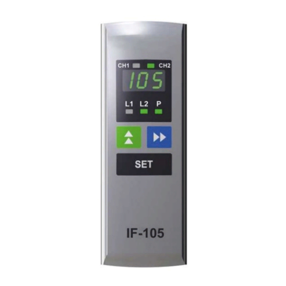
Page 2: General Description
1 (9) MAXILUBE IF-105 USER INTERFACE IF-105 1 GENERAL DESCRIPTION IF-105 is a user interface for MaxiLube lubrication system. Lubrication programming, alarm resetting and lubrication event monitoring can be performed with the user interface. 2 DESIGN Note Numbers in brackets are part numbers of drawing 461981A. The IF-105 user interface includes a display (pos.1), LED-signals for lubrication lines and pressurization (pos.2), browsing buttons (pos.3), a setting/function button (SET) (pos.4) and LED-signals for lubrication channels (pos.5). -
Page 3: Buttons
2 (9) MAXILUBE IF-105 2.3 Buttons Note The operation of the buttons is directed to the channel which is selected on the display. Button Description In normal operation mode, the button is used to browse set values on the display. In setting mode, the button is used to change the value on the display. -
Page 4: Operation
3 (9) MAXILUBE IF-105 3 OPERATION 3.1 Normal mode 3.1.1 Functions Display powersave mode In normal mode display shifts to powersave mode when the buttons have not been used for four (4) minutes. In powersave mode only the decimal points are blinking on the display. Lubrication events are performed according to the set values. -
Page 5: Phase Codes For Normal Mode And Alarm Mode
4 (9) MAXILUBE IF-105 3.1.2 Phase codes for normal mode and alarm mode In normal or alarm mode, the phase code corresponding to the program phase is shown on the display. Phase code Description Pressure discharge waiting time (disCharge) Interlocking switch is closed (Locked) The channel is closed Lubricant barrel low level alarm... -
Page 6: Normal Mode Displays
5 (9) MAXILUBE IF-105 3.1.3 Normal mode displays Normal mode displays, which show lubrication program set values, can be browsed with -button. Display codes change in the following order when -button is pressed. Display code Description The lubrication channel selected on the display. Code is used only in a system with two channels. -
Page 7: Power Failure
6 (9) MAXILUBE IF-105 Pressure switch operation In pressure switch operation, status of the line pressure switches can be displayed with -button. Pressing the button will display status of the line 1 pressure switch first. Code P1 and line 1 pressure switch status are displayed in turns. Pressing the button again will display the status of line 2 pressure switch. -
Page 8: Alarm From Lg-Ind Doser Operation Indicator
7 (9) MAXILUBE IF-105 Alarm, low pressure If the pressure in the line does not rise high enough during pressurization time, code ALP is blinking on the display and the red LED-signal L1 or L2 of the line which has caused the alarm is blinking. -
Page 9: Settings
8 (9) MAXILUBE IF-105 4 SETTINGS 4.1 General Set values are lubrication channel basic values, for example lubrication cycle and maximum pressurization time. Set values are channel specific. All settings are password-protected. 4.2 Entering password Select the code for the setting to be changed on the display with -button. -
Page 10: Lubrication Cycle
9 (9) MAXILUBE IF-105 4.3.2 Lubrication cycle Lubrication cycle set value is displayed as hours and minutes. Decimal point is used to separate hours and minutes. Decimal point of the set value can be moved as follows. Select the code for the setting to be changed on the display with -button.
Need help?
Do you have a question about the MAXILUBE IF-105 and is the answer not in the manual?
Questions and answers