Table of Contents
Advertisement
Quick Links
Installation, Start-Up and Service Instructions
CONTENTS
SAFETY CONSIDERATIONS . . . . . . . . . . . . . . . . . . . . . . . 1
INTRODUCTION . . . . . . . . . . . . . . . . . . . . . . . . . . . . . . . . . . . 2
PREINSTALLATION. . . . . . . . . . . . . . . . . . . . . . . . . . . . . . 2,3
Receiving and Inspection . . . . . . . . . . . . . . . . . . . . . . . . . . 2
Storage . . . . . . . . . . . . . . . . . . . . . . . . . . . . . . . . . . . . . . . . . . . .2
Rigging . . . . . . . . . . . . . . . . . . . . . . . . . . . . . . . . . . . . . . . . . . . .2
Clearance Requirements . . . . . . . . . . . . . . . . . . . . . . . . . . . 3
INSTALLATION . . . . . . . . . . . . . . . . . . . . . . . . . . . . . . . . . . 3-6
Air Handler Unit Pad . . . . . . . . . . . . . . . . . . . . . . . . . . . . . . . 3
Ceiling Suspended Units. . . . . . . . . . . . . . . . . . . . . . . . . . . 3
Roof Curb . . . . . . . . . . . . . . . . . . . . . . . . . . . . . . . . . . . . . . . . .3
Duct/Weather Hood Installation . . . . . . . . . . . . . . . . . . . . 4
Electrical Connections. . . . . . . . . . . . . . . . . . . . . . . . . . . . . 4
Coils . . . . . . . . . . . . . . . . . . . . . . . . . . . . . . . . . . . . . . . . . . . . . . .4
Reassembly of Split Units . . . . . . . . . . . . . . . . . . . . . . . . . 4
Reassembly of Stacked Unit Horizontal Splits. . . . . . 5
Trapping Drains. . . . . . . . . . . . . . . . . . . . . . . . . . . . . . . . . . . . 5
Connecting Ducts. . . . . . . . . . . . . . . . . . . . . . . . . . . . . . . . . . 5
Connecting Rain Hoods. . . . . . . . . . . . . . . . . . . . . . . . . . . . 5
Electrical Installation . . . . . . . . . . . . . . . . . . . . . . . . . . . . . . 5
START-UP . . . . . . . . . . . . . . . . . . . . . . . . . . . . . . . . . . . . . . . . .6
Preliminary Inspection . . . . . . . . . . . . . . . . . . . . . . . . . . . 6
Fan Start-Up . . . . . . . . . . . . . . . . . . . . . . . . . . . . . . . . . . . . . 6
SERVICE . . . . . . . . . . . . . . . . . . . . . . . . . . . . . . . . . . . . . . . . 6-9
Monthly . . . . . . . . . . . . . . . . . . . . . . . . . . . . . . . . . . . . . . . . . . . .6
Every Six Months . . . . . . . . . . . . . . . . . . . . . . . . . . . . . . . . . . 7
Yearly. . . . . . . . . . . . . . . . . . . . . . . . . . . . . . . . . . . . . . . . . . . . . .8
INSTALLATION AND STORAGE CHECKLIST . . . 10,11
SAFETY CONSIDERATIONS
Air-handling equipment is designed to provide safe and reli-
able service when operated within design specifications. To
avoid injury to personnel and damage to equipment or property
when operating this equipment, use good judgment and follow
safe practices as outlined below.
DANGER
NEVER enter an enclosed fan cabinet or reach into a unit
while the fan is running.
LOCK OPEN AND TAG the fan motor power disconnect
switch before working on a fan. Take fuses with you and
note removal on tag. Electric shock can cause personal
injury or death.
LOCK OPEN AND TAG the electric heat coil power dis-
connect switch before working on or near heaters.
Failure to follow these warnings could lead to personal
injury or death.
Manufacturer reserves the right to discontinue, or change at any time, specifications or designs without notice and without incurring obligations.
Catalog No. 04-53390017-01
Page
Printed in U.S.A.
Form 39CC-1SI
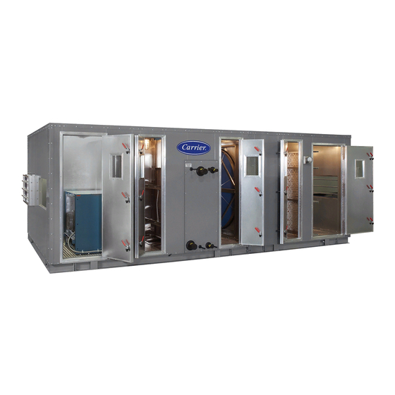
Indoor and Outdoor
Custom Air Handlers
WARNING
CHECK the assembly and component weights to be
sure that the rigging equipment can handle them safely.
Note also, the centers of gravity and any specific rigging
instructions.
CHECK for adequate ventilation so that fumes will not
migrate through ductwork to occupied spaces when weld-
ing or cutting inside air-handling unit cabinet or plenum.
WHEN STEAM CLEANING COILS be sure that the area
is clear of personnel.
DO NOT attempt to handle access covers and removable
panels on outdoor units when winds are strong or gusting
until you have sufficient help to control them. Make sure
panels are properly secured while repairs are being made to
a unit.
DO NOT remove access panel fasteners until fan is com-
pletely stopped. Pressure developed by a moving fan can
cause excessive force against the panel which can injure
personnel.
DO NOT work on dampers until their operators are
disconnected.
BE SURE that fans are properly grounded before working
on them.
Failure to follow these warnings could result in personal
injury or equipment damage.
CAUTION
SECURE drive sheaves with a rope or strap before work-
ing on a fan to ensure that rotor cannot free-wheel.
DO NOT restore power to unit until all temporary walk-
ways inside components have been removed.
NEVER pressurize equipment in excess of specified test
pressures.
PROTECT adjacent flammable material when welding or
flame cutting. Use sheet metal or asbestos cloth to contain
sparks. Have a fire extinguisher at hand and ready for
immediate use.
Failure to follow these warnings could result in personal
injury or equipment damage.
Pg 1
39CCN,CCW
1-15
Replaces: New
Advertisement
Table of Contents

Subscribe to Our Youtube Channel
Related Manuals for Carrier 39CCN


Summary of Contents for Carrier 39CCN
-
Page 1: Table Of Contents
39CCN,CCW Indoor and Outdoor Custom Air Handlers Installation, Start-Up and Service Instructions CONTENTS WARNING Page CHECK the assembly and component weights to be SAFETY CONSIDERATIONS ..... . . 1 sure that the rigging equipment can handle them safely. -
Page 2: Introduction
(for example, PREINSTALLATION more weight in the coil and fan areas). In case where the unit’s center of gravity is a concern, please contact your Carrier rep- Receiving and Inspection resentative. 1. Verify receipt of all parts by comparing items in the ship- Prior to lifting, install the removable lugs shipped loose in ment with those listed on the bill of lading. -
Page 3: Split Units
It is mandatory to use spreader bars for larger units with lift- installer’s responsibility to secure the unit to the unit pad in ac- ing lugs or slings for smaller units to prevent damage to the cordance with all applicable building and earthquake codes. casing of the units by rigging equipment. -
Page 4: Duct/Weather Hood Installation
5. Roof the curb prior to setting the unit. Use standard 2 in. x • control valve chattering 4 in. wood nailers (provided), insulate and flash (by oth- • internal corrosion from chemicals in fluid ers) as required. • external corrosion from chemicals in the air stream 6. -
Page 5: Reassembly Of Stacked Unit Horizontal Splits
CAULKING a39-4467 Fig. 7 — Caulking Roof Exterior Seams • Caulk and bolt standing seam and install the roof cleat. When connecting flanged ducts Connecting Ducts — See Fig. 8. directly to the casing, use self-tapping sheet metal screws. For duct connections to collar-type openings, use s-cleats or over- lapping joints. -
Page 6: Start-Up
1-¼ IN. MP SLOPE IN. PER FT MIN. CLEAN OUT SLOPE IN. PER FT MIN. a39-4468 (+) STATIC PRESSURE (-) STATIC PRESSURE (DRAW THROUGH COIL) (BLOW THROUGH COIL) — TSP + 1 in. — 1 in. — TSP + 1 in. —... -
Page 7: Recommended Grease
WIRE TUBE NUTS STUD SHOULDER SHOULDER WASHER STUD WASHER TUBE STUB SHOULDER TUBE ½ IN. WASHER SHIPPING POSITION EXPANDED OPERATING POSITION a39-4469 SIDE VIEW SIDE VIEW ASSEMBLY VIEW Fig. 10 — Fan Assembly Table 1 — Ball Bearing Lubrication Schedule APPROX. -
Page 8: Yearly
with field-modified drives, use the deflection formula in 6. Compare the force you have applied with the values giv- the following example and the tension data from Table 3. en in Table 3. The force should be between the “Used Belt”... - Page 9 Table 3 — Fan Belt Tension Data BELT DEFLECTION FORCE (lb) SMALLEST SUPER GRIPBELTS AND UNNOTCHED GRIPNOTCH BELTS AND NOTCHED BELT STYLE SHEAVE DIAMETER RPM RANGE GRIPBANDS GRIPBANDS RANGE (in.) USED BELT NEW BELT USED BELT NEW BELT 1000-2500 3.0 - 3.6 2501-4000 1000-2500 A, AX...
-
Page 10: Installation And Storage Checklist
INSTALLATION AND STORAGE CHECKLIST UNIT FAN SAFETY Visually inspect wheel and fan rotation. Lockout power supplies before opening access doors. _____ _____ Inertia base is fitted. Prevent wheel rotation during fan servicing. _____ _____ Replace belt guards or fan safety screen after installa- Shipping tie downs are removed. - Page 11 ELIMINATORS AND DAMPERS Equipment has been visually inspected for damage; _____ damaged blades/linkage repaired. Check that low-leak damper edge and blade seals are in _____ place and not loose. Manually operate each damper through cycle to verify _____ operation and complete closure. Actuators are installed.
- Page 12 © Carrier Corporation 2015 Manufacturer reserves the right to discontinue, or change at any time, specifications or designs without notice and without incurring obligations. Catalog No. 04-53390017-01 Printed in U.S.A. Form 39CC-1SI Pg 12 1-15 Replaces: New...
Need help?
Do you have a question about the 39CCN and is the answer not in the manual?
Questions and answers