Table of Contents
Troubleshooting

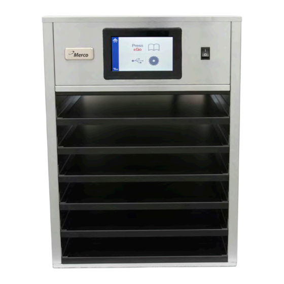
Related Manuals for Merco MHU63SST2N


Summary of Contents for Merco MHU63SST2N
- Page 1 Serving Quality on Demand Visual Holding Cabinet (MHU) Service Manual This manual is updated as new information and models are released. Visit our website for the latest manual. *8197925* Part Number: MER_SM_8197925 09/2020...
- Page 2 Safety Notices Warning Use caution when handling metal surface edges of all Warning equipment. Read this manual thoroughly before operating, installing or performing maintenance on the equipment. Failure Warning to follow instructions in this manual can cause property This appliance is not intended for use by persons damage, injury or death.
-
Page 3: Table Of Contents
Table of Contents Section 1 General Information Model Numbers .......................1-1 Serial Number Information ....................1-1 Warranty Information .....................1-1 Regulatory Certifications ....................1-1 Section 2 Installation Location ...........................2-1 Weight of Equipment ......................2-2 Clearance Requirements ....................2-2 Dimensions ........................2-2 Electrical Service ......................2-2 Voltage, Watts, Rated Amperages & Power Cord Chart ............2-2 Section 3 Operation Power Switch ........................3-1... - Page 4 Table of Contents (continued) Instructions For Replacing an IO Board ..................4-6 I/O Board Switch and Jumper Settings..................4-6 I/O Board ...............................4-7 Section 5 Troubleshooting Troubleshooting ......................5-1 Zone Diagnostics ..........................5-1 Power Issues Troubleshooting .......................5-2 Communication Issues Troubleshooting ...................5-3 Temperature Too Low/Self Temp Low Issues Troubleshooting .........5-4 Temperature Too High Issues Troubleshooting ...............5-5 Display Issues Troubleshooting .....................5-6 ID Connector Issues Troubleshooting ..................5-7...
-
Page 5: General Information
Always have the serial number of your unit available when calling for parts or service. Service Personnel All service on Merco equipment must be performed by qualified, certified, licensed, and/or authorized or service personnel. Qualified service personnel are those who are familiar with Merco equipment and who have been authorized by Merco to perform service on the equipment. -
Page 6: Installation
Section 2 Installation Location DANGER Installation must comply with all applicable fire and Warning health codes in your jurisdiction. This equipment must be positioned so that the plug is accessible unless other means for disconnection from DANGER the power supply (e.g., circuit breaker or disconnect Carts must be installed and the carts must be screwed switch) is provided. -
Page 7: Weight Of Equipment
Installation Section 2 Weight of Equipment Electrical Service Domestic Model Weight DANGER MHU63SST2N 120lbs (54kg) Check all wiring connections, including factory terminals, before operation. Connections can become Clearance Requirements loose during shipment and installation. DANGER DANGER Minimum clearance requirements are the same for Copper wire suitable for at least 167°F (75°C) must be... -
Page 8: Operation
Section 3 Operation The Merco Visual Holding Cabinet has been designed to DANGER afford food service operators the ability to cook menu The on-site supervisor is responsible for ensuring that components in advance and then gently store that product operators are made aware of the inherent dangers of in the holding bins until an order is received. -
Page 9: User Interface
Operation Section 3 User Interface The unit will beep signaling that all holding zones are pre- heated and ready for use. PASSWORD • A user can access all necessary screens for daily operation without a password. • The factory default manager password is 2580. PRESS &... - Page 10 Section 3 Operation The green portion of the tray timer represents the The alarm will beep for 10 seconds. The timer will display remaining time. Each menu item has a programmed time the product is being held past programmed hold time. warning time.
-
Page 11: Tray Specifications
Operation Section 3 TRAY SPECIFICATIONS A Group in the Menu Use First For Identical Products A product in the menu is part of a group if there are dots underneath it or arrow heads on either side of it. Select the When two identical products are active, the one with the menu item with the dots and the other items in the group least time remaining will be highlighted in green, the others... - Page 12 Section 3 Operation On press and go screen the lock icon disables the touch screen for 10 seconds. The lock icon must be held for 1 second to disable the screen. In the center of the lock graphic the 10 seconds will be counted down. Ten seconds of disabled screen allows time for the touch screen to be cleaned.
-
Page 13: Menu Screens
Operation Section 3 MENU SCREENS Select the unwanted product and then the delete icon, X. A confirmation widow will pop up. Select the green check to From the home screen selecting the menu icon brings up delete the product. Select the red X to return to the menu the menu screen. - Page 14 Section 3 Operation On the menu screen are navigation icons. If the group page is unlocked, the delete, edit and add icons will display on the group screen. • The first icon returns you to the product list screen. • The second takes you to the group list screen .
- Page 15 Operation Section 3 Select the group to be edited and the edit icon, a pencil. In To add a group, select the group page add icon, +. A pop up the pop up window the group will appear. You can edit the window will appear.
-
Page 16: Setting Screens
Section 3 Operation On the menu screen are navigation icons. Next to the back SETTING SCREENS arrow is the day part edit icon. From the home screen selecting the settings icon brings up the preferences screen. This is the first of eleven setting screens. -
Page 17: Preferences Screen
Operation Section 3 PREFERENCES SCREEN DATE & TIME SCREEN To make changes on the preferences screen a passcode To make changes on the this screen a passcode must be must be entered. Select the lock on the bottom left of the entered. -
Page 18: Language Screen
Section 3 Operation LANGUAGE SCREEN CABINET NAMES SCREEN To make changes on the this screen a passcode must be To make changes on the this screen a passcode must be entered. Select the lock on the bottom left of the screen. entered. -
Page 19: Zone Diagnostics Screens
Operation Section 3 ZONE DIAGNOSTICS SCREENS SOUND & SCREEN TESTS Holding cabinet temperatures can be monitored on this This screen does not require a passcode. screen, no password is required to observe current heating element temperatures. To run service tests on the this screen a service passcode must be entered. -
Page 20: Errors Log Screen
Section 3 Operation ERRORS LOG SCREEN PASSWORD SETTINGS SCREEN This screen does not require a passcode. Errors Log Screen Password Settings Screen Clear all button removes all entries on the errors log screen. There is a factory default manager passcode. It can be Touching the Refresh button will update the error list. -
Page 21: System Information Screen
Operation Section 3 SYSTEM INFORMATION SCREEN UTILITIES SCREEN This screen does not require a passcode, there are no To run demo mode on the utility screen a service passcode actions available on this screen. must be entered. Select the lock on the bottom left of the screen. -
Page 22: Load New Software Via Usb
Section 3 Operation Load New Software Via USB UI BOARD UPDATE 1. Firmware update files work for all models. 2. Verify the files and file names are correct on the UI USB. MHU software file folder name: vhcupdate MHU software file name: vhclfb Product menu file name: productsList.txt 3. -
Page 23: Maintenance
Section 4 Maintenance Cleaning and Sanitizing Procedures DANGER All utility connections and fixtures must be maintained GENERAL in accordance with Local and national codes. You are responsible for maintaining the equipment in accordance with the instructions in this manual. DANGER Maintenance procedures are not covered by the warranty. -
Page 24: Interior Cleaning
Maintenance Section 4 INTERIOR CLEANING DAILY CLEANING INSTRUCTIONS 1. You will need a damp cloth and hot soapy water. Caution 2. Turn the unit off. Do not use caustic cleaners on any part of the holding cabinet or holding cabinet cavity . Use mild, non abrasive soaps or detergents, applied with a sponge or soft cloth. - Page 25 Section 4 Maintenance 8. Wipe the stainless steel exterior with a damp cloth, rubbing with the grain of the steel. If an excessive amount of food particles/grease has collected, hot sudsy water (non-abrasive) may be used. 9. Wipe the interior with a damp cloth; clean from the front and the back to reach all surfaces.
-
Page 26: Component Identification
Maintenance Section 4 Component Identification Front Controller Power Switch Speaker Slave 1 I/O board Power Supply Slave 2 I/O board Relay I/O Board Master Rear Controller Circuit Breaker... -
Page 27: Instructions For Replacing A Heater Pad
Section 4 Maintenance INSTRUCTIONS FOR REPLACING A HEATER PAD locks in place. Pad heater probes are located in the heater pad assembly. Reattach any cables or wires and attach the top of the NOTE : Failed thermocouples require a heater pad cabinet. -
Page 28: Instructions For Replacing An Io Board
Maintenance Section 4 Caution INSTRUCTIONS FOR REPLACING AN IO BOARD 1. Disconnect power. Ensure switches jumper match the old I/O Board upon replacement. 2. Remove the top of the cabinet. When the jumper is in the wrong position, zones will 3. -
Page 29: I/O Board
Section 4 Maintenance I/O Board Caution I/O Board must be loaded with software. A sticker will indicate when software is loaded and part number to indicate software version. Thermocouple terminals switches To Power Supply Controller To Slave IO Board From Master IO Board Jumper... -
Page 30: Troubleshooting
Section 5 Troubleshooting The software shall track the state of each thermocouple and the state of the thermocouple reading compared to the set point. If the software finds an error, it will begin to time it. When the timer reaches 15 minutes, an error code(s) will display (flash) on the screen. - Page 31 Troubleshooting Section 5...
- Page 32 Section 5 Troubleshooting...
- Page 33 Troubleshooting Section 5...
- Page 34 Section 5 Troubleshooting...
- Page 35 Troubleshooting Section 5...
- Page 36 Section 5 Troubleshooting...
-
Page 37: Heater/Thermocouple Troubleshooting
Troubleshooting Section 5 Heater/Thermocouple Troubleshooting Check ohm resistance on heater pad. The ohms and part number are below. Thermocouple Reading is Below or Above Set Point - 8076230 - 6x3 144.5 Ω (137 Ω – 152 Ω) Zone Error is displayed on screen 1. -
Page 38: Wiring Diagrams
Section 6 Wiring Diagrams MHU63 - 6x3 Wiring... - Page 39 THIS PAGE INTENTIONALLY LEFT BLANK...
- Page 40 MERCO 8700 LINE AVENUE, SHREVEPORT, LA 71106-6800 MERCO SALES: 800.221.4583 MERCO SERVICE: 877.392.7770 Serving Quality on Demand WWW.MERCOPRODUCTS.COM WWW.WELBILT.COM Welbilt provides the world’s top chefs, and premier chain operators or growing independents with industry leading equipment and solutions. Our cutting-edge designs and lean manufacturing tactics are powered by deep knowledge, operator insights, and culinary expertise.
Need help?
Do you have a question about the MHU63SST2N and is the answer not in the manual?
Questions and answers