
Related Manuals for Merco Insta-Therm 16000 Series


Summary of Contents for Merco Insta-Therm 16000 Series
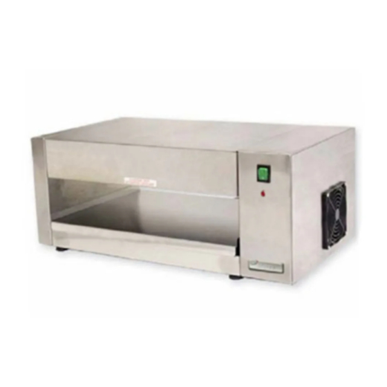
- Page 1 PARTS & SERVICE MANUAL Insta-Therm 16000 Series P/N: L340136 REV: 8.2.10 Merco, LLC 1111 North Hadley Road Fort Wayne, Indiana 46804 Telephone: 260.459.8200 Fax: 888.790.8193 Technical Support: 800.678.9511 mercosavory.com...
-
Page 2: Unit Specifications
UNIT SPECIFICATIONS Unit # Volts Amps Watts Phase Cord/Plug Weight 16001* 11.25 2340 Single 6’ NEMA 6-20P 47 lbs. / 21.3 kg. 16003** 9.91 2280 Single CEE 7/7 47 lbs. / 21.3 kg. 16005 11.25 2340 Single 6’ NEMA 6-20P 47 lbs. - Page 3 SCHEMATIC MODEL 16001 Insta-Therm Service Manual...
- Page 4 SCHEMATIC MODEL 16003, 16005 Insta-Therm Service Manual...
-
Page 5: Sequence Of Operation
SEQUENCE OF OPERATION POWER SUPPLY Electrical power is supplied to the unit by a 3 conductor service for single phase. Black conductor is hot. White conductor is neutral. Green and Yellow conductor is ground. Power is permanently supplied to the power switch through the high limit thermostat. -
Page 6: Troubleshooting
TROUBLESHOOTING SYMPTOM POSSIBLE CAUSE EVALUATION Unit will not turn on Incoming Power Supply Check breakers, reset if required. Check power plug to be sure it’s firmly in receptacle. Measure incoming power 208v Hi Limit Thermostat Terminals are normally closed, if open push in reset button. - Page 7 This page intentionally left blank. Insta-Therm Service Manual...
-
Page 8: Parts Breakdown
369331 Finger Guard 369378 Fan Motor 340036 Solid State Relay 340037 Terminal Block, X3 27511SP Switch, Rocker, Lighted 10004115 Wire Guard 340039 Merco Logo 340132 Shelf Not Shown 19378SP Micro Switch Not Shown 369507 Thermostat Bi-Metal (cooldown) Insta-Therm Service Manual... -
Page 9: Exploded-View Illustration
EXPLODED VIEW ILLUSTRATION Insta-Therm Service Manual... -
Page 10: Heater Installation Instructions
HEATER INSTALLATION INSTRUCTIONS Disconnect power supply before servicing or cleaning this toaster. Safeguard power DANGER: so it cannot be accidentally restored. Failure to do so could result in serious injury. Heater elements must not be handled with bare hands. Oil or grease residue on the CAUTION: quartz tube may result in premature failure of the element. - Page 11 HEATER INSTALLATION INSTRUCTIONS (CONT’D) STEP 3 – INSTALLING HEATER ELEMENTS DO NOT TOUCH QUARTZ HEAT TUBES WITH BARE HANDS. USE GLOVES CAUTION: WHILE HANDLING TUBES. Slide the heater elements (quartz tubes) through the holes in the right hand wall of the unit, feeding the lead wires through the hole in the left hand wall and heater support bracket.
- Page 12 HEATER INSTALLATION INSTRUCTIONS (CONT’D) STEP 4 – REINSTALLATION OF HEATER SUPPORT BRACKET Reposition the right side heater support bracket over the ends of the heater element, feeding the lead wires through the holes. Secure using the screws previously removed. Right Side Heater Support Bracket STEP 5 –...
- Page 13 HEATER INSTALLATION INSTRUCTIONS (CONT’D) STEP 6 – CONNECTING RIGHT SIDE HEATER WIRES Connect the four (4) heater wires on the right side to the terminal block as shown. Heater wire #1 and #2 are connected to terminal block position #3, heater wire #3 to terminal block position #2, and heater wire #4 to terminal block position #1.
- Page 14 This page intentionally left blank. Insta-Therm Service Manual...
- Page 15 This page intentionally left blank. Insta-Therm Service Manual...
- Page 16 Insta-Therm Service Manual...
Need help?
Do you have a question about the Insta-Therm 16000 Series and is the answer not in the manual?
Questions and answers