Table of Contents
Advertisement
Quick Links
Advertisement
Table of Contents

Subscribe to Our Youtube Channel
Related Manuals for Burkert MS09


Summary of Contents for Burkert MS09
- Page 1 Type MS09 Nitrate Sensor Operating Instructions...
- Page 2 We reserve the right to make technical changes without notice. © Bürkert SAS, 2021 Operating Instructions 2110/00_EU-ML 00572429 / Original EN...
-
Page 3: Table Of Contents
5 Installation .............................. 25 Safety instructions .......................... 25 Installing procedure ........................ 25 6 Electrical connection.......................... 28 Connection plan MS09 ........................ 28 Connection plan ME63 ........................ 29 Assignment of the connections ...................... 29 Supply voltage .......................... 31 M12 8 pins Nitrate Sensor connection ................... 31 7 Commissioning ............................ 33... - Page 4 Type MS09 Table of contents Manufacturer calibration......................... 33 Path length check........................... 33 7.3.1 Turbidity and organics compensation ................ 33 7.3.2 Nitrite .......................... 33 7.3.3 Salinity .......................... 34 7.3.4 Path lengths and limit values ..................... 34 7.3.5 Unknown substances ...................... 35 Install the micro SD card ........................ 35 Transfer data to or from another product..................
- Page 5 Type MS09 Table of contents 12.3 Enter the location of the product.................... 57 12.4 Enter a description for the product .................... 57 12.5 Enter a unique name for the product.................... 57 12.6 Change the transmission speed of the product ................ 57 12.7 Address of a product connected to büS ..................
- Page 6 Sensor error (UPS error). Contact the service for your device ....... 83 16.6.3 Message Sensor error (power fail detected). Contact the service for your device.. 84 16.6.4 Message Transferable memory is not accessible ............ 84 17 Spare parts and accessories ........................ 85 17.1 MS09 Nitrate Sensor accessories .................... 85 18 Uninstallation ............................ 86...
- Page 7 Type MS09 Table of contents 18.1 Safety instructions .......................... 86 18.2 Uninstalling procedure........................ 86 19 Logistic .............................. 87 19.1 Transport ............................ 87 19.2 Storage ............................ 87 19.3 Return ............................. 87 19.4 Disposal ............................ 87...
-
Page 8: About This Document
▪ Before starting any work on the product, read and observe the respective sections of the document. ▪ Keep the document available for reference and give it to the next user. ▪ Contact the Bürkert sales office for any questions. Further information concerning the product at country.burkert.com. Manufacturer Bürkert SAS... -
Page 9: Terms And Abbreviations
Type MS09 About this document Terms and abbreviations The terms and abbreviations are used in this document to refer to following definitions. Product MS09 ▪ Photometer, digital büS Bürkert system bus, a communication bus developed by Bürkert and based on the... -
Page 10: Safety Instructions
MS09 is used exclusively for the implementation of NO3 or photometric measurements as described in this manual. The product has been developed for use in industrial an municipal water treatment plants. The ME63 Sensor Interface is used to connect the Sensor Types MS08 and MS09 into Bürkert büS net- works. - Page 11 Type MS09 Safety instructions To prevent injuries and product damage, observe the following: ▶ Install the product according to the regulations applicable in the respective country. ▶ Make sure only trained technicians carry out installation and maintenance work. ▶ Secure the product or system to prevent unintentional activation.
- Page 12 Type MS09 Safety instructions DANGER! Bürkert does not guarantee the plausibility of the measured values. The user is always responsible for the monitoring and interpretation of the measured values. CAUTION! Electrostatically sensitive components and assemblies. The product contains electronic components that are susceptible to the effects of electrostatic dischar- ging (ESD).
-
Page 13: Product Description
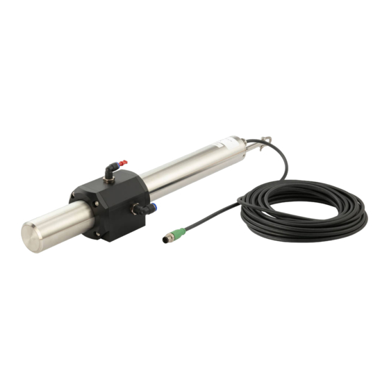
Type MS09 Product description PRODUCT DESCRIPTION Design The MS09 consists of the following components: Fig. 1: MS09 components 1 Nitrate Sensor 2 Flow cell 3 Connecting cable 4 ME63 Sensor interface 3.1.1 ME63 Sensor Interface Fig. 2: View of ME63 type 1 X1... -
Page 14: Ms09 Nitrate Sensor
10 Cover with 2 screws, slot for micro SD card 11 X01, X02: D-coded connection 12 X03 (IN), X04 (OUT): L-coded connection, 24 V DC 13 Earth connection 3.1.2 MS09 Nitrate Sensor Fig. 3: View of Nitrate Sensor Fig. 4: Nitrate Sensor dimensions 3.1.3 Flow cell... -
Page 15: Display Elements
Type MS09 Product description Fig. 5: View of flow cell Fig. 6: Flow cell dimensions Display elements Type ME63 has LEDs for diagnostics on the product status: Fig. 7: Display elements for ME63 type 1 Product status indicator. The indicator op- 2 Communication status indicator 1. The in- erates according to NAMUR NE 107. -
Page 16: Product Status Indicator
Type MS09 Product description 5 Link/Act Blinking - There is activity on this port. Off - No link is etablished 3.2.1 Product status indicator The product status indicator changes its colour based on the NAMUR recommendation NE 107. The colour of the product status indicator gives the following pieces of information: ▪... -
Page 17: Markings
To solve a problem indicated by the product status indicator, refer to chapter: Troubleshooting [} 78]. Markings 3.3.1 Type label 3.3.1.1 ME63 Sensor Interface Fig. 8: ME63 Label 3.3.1.2 Nitrate Sensor Fig. 9: Nitrate Sensor Label 3.3.1.3 Flow cell Fig. 10: MS09 Flow cell Label... -
Page 18: Conformity Marking
Operating principle The ME63 Sensor Interface represents the central control unit for MS08 and MS09. Function: The ME63 Sensor Interface is an additional interface for büS devices. The ME63 Sensor Interface exchanges data with the Nitrate Sensor on Ethernet communication. - Page 19 Type MS09 Product description ▪ a defined light source ▪ a lens system ▪ the optical path through the medium ▪ a second lens system with three photodiodes as detectors A xenon flash lamp is used as a broadband light source. The light passes through the medium in the optical path and is partially absorbed by it.
- Page 20 Type MS09 Product description Parameters The Nitrate sensor measures absorption at 212 nm. The derived parameter NO is output. Taking the path length into account, the absorption values [AU] are calculated with the unit [1/m] at 212, 254 and 360 nm. The Nitrate sensor uses the absorption at 212 nm for the detection of NO -N.
- Page 21 Type MS09 Product description ▪ RefB indicates the light intensity on the 254 nm channel. ▪ RefC indicates the light intensity on the 360 nm channel. ▪ RefD indicates the light intensity of the reference diode. Details and limit values of the reference parameters can be found in chapter Path lengths and limit values [} 34]...
-
Page 22: Technical Data
Type MS09 Technical data TECHNICAL DATA Operating conditions Ambient temperature -20 °C…+60 °C IP-Code according to IP65 and IP67 EN 60529 If the following condition is met: connections are fitted with protective caps Tab. 3: ME63 Sensor Interface: Operating conditions Ambient temperature +2 °C…+40 °C Fluid temperature +2 °C…+40 °C... -
Page 23: Dimensions, Weight
Type MS09 Technical data Dimensions, weight Refer to the data sheet of the related product. Performance data Parameters (calibrated with NO standard solution) Measurement range see parameter list below Measurement accuracy see parameter list below Turbidity compensation Data Logger ~ 2 GB Reaction time T100 20 s... -
Page 24: Fluid Data
Type MS09 Technical data Path length Parameters Measurement Detection Determination Precision Accuracy [mm] range limit limit Nitrate 0…6 0.05 0.15 0.015 ± (5 % + 0.1) Nitrate NO 0…26.6 0.22 0.66 0.066 ± (5 % + 0.44) Nitrate 0…3 0.025 0.075 0.0075 ± (5 % + 0.05) -
Page 25: Installation
Type MS09 Installation INSTALLATION Safety instructions WARNING! Risk of injury due to improper installation. ▶ Only trained technicians may perform installation work. ▶ Perform installation work using suitable tools only. CAUTION! Malfunction due to electrostatic discharge. Electrostatic discharge on the product may cause malfunctions. - Page 26 Type MS09 Installation ▪ There is a 6-mm outlet hose connection on the left side of the cell. ▪ There is a third hose connection on the top of the cell which can be used for cleaning with fluids. If this inlet is not being used, it should be sealed with a plug.
- Page 27 Type MS09 Installation Slide a seal over the Nitrate Sensor in the slots provided in the flow cell cuvette. Before final assembly, please check seals for damage and use new ones where necessary. Seals (48 x 5 mm NBR) are avail- able as spare parts and can be purchased from Bürkert.
-
Page 28: Electrical Connection
Electrical connection ELECTRICAL CONNECTION Connection plan MS09 Fig. 17: Connection plan MS09 1 ME63 Sensor interface 2 MS09 Ethernet cable (blue colour): X01 or 3 Cable 4 Nitrate Sensor 5 Flow cell 6 MS09 power supply cable: X1–X3, X5–X8 7 M12 terminating resistor: X1–X3, X5–X8 8 Burkert büS input (CAN + power supply): X4... -
Page 29: Connection Plan Me63
Electrical connection Connection plan ME63 Fig. 18: Connections ME63 Sensor interface (detail) 2 MS09 Ethernet cable (blue colour): X01 or 6 MS09 power supply cable: X1–X3, X5–X8 7 M12 terminating resistor: X1–X3, X5–X8 8 Burkert büS input (CAN + power supply): X4... - Page 30 Type MS09 Electrical connection Port Function Pin 1 Pin 2 Pin 3 Pin 4 Pin 5 X4 (IN) CAN + power CAN_GND 24 V CAN_H CAN_L supply Tab. 13: Assignment of the connections Assignment Function Send data + Receive data + Send data - Receive data - Tab. 14: Connections M12, X01, X02 (socket), D-coded...
-
Page 31: Supply Voltage
Type MS09 Electrical connection Supply voltage Fig. 19: Supply options 1 Supply via A-coded connection, max. 4 A, 2 Return flow is prevented via reverse protec- automatic detection tion 3 24 V/32 A source 1 4 24 V/32 A source 2 5 Supply via L-coded connection, max. - Page 32 Type MS09 Electrical connection Assignment Function RS-232 RX / RS-485 A (commands) RS-232 TX / RS-485 B (data) ETH_RX- ETH_RX+ ETH_TX- ETH_TX+ Ground (Power + Ser. In- terface) Power (24 VD C) Tab. 17: Nitrate Sensor: M12 8 pins connections Ensure correct polarity of the operating voltage or otherwise the sensor may be damaged.
-
Page 33: Commissioning
Type MS09 Commissioning COMMISSIONING Safety instructions WARNING! Risk of injury from improper operation. Improper operation can lead to injuries and damage to the product and its environment. ▶ Before commissioning, make sure that the operating personnel are familiar with, and fully understand the content of the Operating Instructions. -
Page 34: Salinity
Type MS09 Commissioning Path length 10 mm Measurement at 212 nm Nitrite 3.5 mg/L Nitrate 2.1 mg/L Wavelength [nm] 7.3.3 Salinity Please note that the optical determination of nitrate in connection with high salt concentrations (≥ 1 PSU) can lead to interference. The salinity absorbs light of the same wavelength range. The figure below shows the absorption curves of nitrate (2.1 mg/L) and salinity of seawater (35 PSU). -
Page 35: Unknown Substances
Type MS09 Commissioning The following table lists the limit values of the reference values RefA, RefB, RefC and SQI for checking the sensor in the application. Reference value Explanation Lower limit value Recommendation RefA Light intensity on the Check the sensor and, if 212 nm channel... -
Page 36: Transfer Data To Or From Another Product
Type MS09 Commissioning Open the micro SD card slot: Unfasten the 2 screws using a cross-tip screwdriver and open the cover. Insert the micro SD card: Slide the micro SD card into the card slot. Ensure that the micro SD card locks into position. - Page 37 Type MS09 Commissioning Step 4: Restart the product Please note that a newly installed micro SD card is checked for the presence of existing data. Refer to chapter Install the micro SD card [} 35]...
-
Page 38: Setting And Operation
▪ the Type ME21 touchscreen of the Type 8905 system. To get general information about the Type ME21 touchscreen, refer to the Type ME25 Operating Instructions that are available on the CD delivered with the system and that are also available at country.burkert.com. These Operating Instructions describe the product-specific settings that are made with the Type ME21 touchscreen. -
Page 39: Available Login User Levels
Type MS09 Setting and operation ▪ the product functions. Each function has 3 menus. Refer to chapter Product functions and menus [} 40]. ▪ the Messages overview, overview of the messages that are related to both the system and the product. -
Page 40: Product Functions And Menus
Type MS09 Setting and operation Product functions and menus The product has 2 functions and each function has 3 menus. To access the product functions and the menus, do the following procedure: Press that is located under the touchscreen. Select < or > to display the Device view. -
Page 41: Sensor - Parameter
Type MS09 Sensor - Parameter SENSOR - PARAMETER Go to device Nitrate Sensor > function Sensor > tab Parameter. Detailed view Parameter Setting Sensor Select the type of sensor connected to the ME63 interface. Organic compensa- Set the level for organic compensation. -
Page 42: Define The Organic Compensation Level
Type MS09 Sensor - Parameter Select Sensor. Select the sensor type from the drop-down list: For the MS09, select NO3. After changing the sensor type, the device has to be restarted. The device restarts with the selected sensor type. Define the organic compensation level Optical nitrate measurement can be influenced by the presence of organic substances (organics). -
Page 43: Monitor The Values Of The Water Sample
Type MS09 Sensor - Parameter The customer calibration supplements the manufacturer calibration. The manufacturer calibration values are not changed by the customer calibration. Customer calibration can be used as a fine adjustment of the sensor for special media and is not intended to replace the manufacturer calibration. -
Page 44: Freeze The Values Transmitted On The Fieldbus
Type MS09 Sensor - Parameter Select the desired parameter and enter a value under which a diagnostic event (Out of specification) and a warning message are generated. The product status indicator is yellow (refer to chapter Product status indicator [} 16]). -
Page 45: Manual Freeze
Type MS09 Sensor - Parameter 9.6.1 Manual freeze Access to parameter Hold value Make sure that the login user level is Installer. Refer to chapter Available login user levels [} 39]. Go to device Nitrate Sensor > function Sensor > tab Parameter. -
Page 46: Change The Binary Event For The Automatic Freeze
Type MS09 Sensor - Parameter Select a device in the list. The available binary events are displayed. Select the binary event. Validate with Apply. The next step restarts the product. Select Finish to set the connection. The product restarts. Go to the Device connections view to make sure that the connection is set. -
Page 47: Stop The Manual Freeze Or The Automatic Freeze
Type MS09 Sensor - Parameter The next step restarts the product. Select Finish to restart the product. The product restarts. 9.6.4 Stop the manual freeze or the automatic freeze Access to parameter Hold value Make sure that the login user level is Installer. Refer to chapter Available login user levels [} 39]. -
Page 48: Sensor - Diagnostics
Type MS09 Sensor - Diagnostics SENSOR - DIAGNOSTICS Go to device Nitrate Sensor > function Sensor > tab Diagnostics. Detailed view Diagnostics In these menus, the current values are displayed, not set. Setting General Information Read information about the sensor. -
Page 49: Check Sensor Information
Type MS09 Sensor - Diagnostics ▪ Calibration, refer to chapter Check calibration values [} 49]. ▪ Measure values, refer to chapter Check measured values [} 49]. ▪ Advanced, refer to chapter Check values for advanced diagnostics [} 50]. 10.1 Check sensor information The values displayed under General information show information about the connected sensor. -
Page 50: Check Values For Advanced Diagnostics
Type MS09 Sensor - Diagnostics The values are shown. See Table Description of the measured values parameters [} 50] for a de- scription. Parameter Description Quality index Nitrate Tab. 24: Description of the measured values parameters 10.4 Check values for advanced diagnostics... -
Page 51: Sensor - Maintenance
Type MS09 Sensor - Maintenance SENSOR - MAINTENANCE Go to device Nitrate Sensor > function Sensor > tab Maintenance. Detailed view Maintenance Setting Simulation Status Start or stop the simulation mode and enter simulated data. Start measurement Wizard to manually start a measurement. -
Page 52: Manually Start A Measurement
Type MS09 Sensor - Maintenance Select the measure value you want to simulate and enter the desired value. Validate with Apply. Repeat for any value you want to simulate. The product status indicator is orange. For the meaning of the signal of the product status LED, refer to chapter Product status indicator [} 16]. -
Page 53: Plan The Calibrations
Type MS09 Sensor - Maintenance To continue, select Next. The wizard page displays requirements to check before the calibration. Check the requirements displayed on the wizard page. To start the calibration, select Next. The calibration process starts, the wizard page displays status messages. - Page 54 Type MS09 Sensor - Maintenance Go to device Nitrate Sensor > function Sensor > tab Maintenance. Select Service mode. To activate the service mode, select On. The IP address of the sensor is displayed. Values are not updated anymore. To deactivate the service mode, select Off.
-
Page 55: General Settings - Parameter
Type MS09 General Settings - Parameter GENERAL SETTINGS - PARAMETER Go to device Nitrate Sensor > function General settings > tab Parameter. Detailed view Parameter Setting Status LED Mode büS Configuration of the büS interface Displayed name For display and Bürkert Communicator Location Specify location displayed for the device. -
Page 56: Set The Colours And Behaviour Of The Device Status Led
Type MS09 General Settings - Parameter The menu items are detailed in the following chapters: ▪ Status LED, refer to chapter Set the colours and behaviour of the device status LED [} 56]. ▪ büS, refer to chapter Enter a name for the product [} 56],... -
Page 57: Enter The Location Of The Product
Type MS09 General Settings - Parameter 12.3 Enter the location of the product The entered location will be shown on any display connected to büS. To enter the information where the product is located, do the following procedure: Make sure that the login user level is Installer. Refer to chapter Available login user levels [} 39]. -
Page 58: Address Of A Product Connected To Büs
Type MS09 General Settings - Parameter Make sure that the login user level is Installer. Refer to chapter Available login user levels [} 39]. Go to device Nitrate Sensor > function General settings > tab Parameter. Select büS > Advanced >... -
Page 59: Set The Canopen Status
Type MS09 General Settings - Parameter Select büS > Advanced > mode. Select the operating mode büS CANopen from the drop-down list. Validate with Apply. The operating mode of the digital communication is changed. If the operating mode of the digital communication is set to büS... -
Page 60: Change The Time To Check The Presence Of A Participant On The Fieldbus
Type MS09 General Settings - Parameter Select Standalone. Validate with Apply. Restart the product to take the operating mode of digital communication into account. The PDOs are no more sent to the connected fieldbus. 12.14 Change the time to check the presence of a participant on the fieldbus Bürkert recommends not to change the parameter... -
Page 61: Monitor The Device Temperature
Type MS09 General Settings - Parameter 12.16 Monitor the device temperature The parameters at Alarm limits make it possible to monitor the device temperature and issue a warning or error in case of too low or too high temperature. The alarm limits for warnings can be set by the user. The alarm limits for errors and hysteresis are read- only. - Page 62 Type MS09 General Settings - Parameter By default, the diagnostics are enabled. The product status are shown according to Table Product status when the diagnostics are enabled [} 62]. Product status indicator Colour code (for Displayed sym- Description Meaning a PLC)
-
Page 63: Set The Transmission Time Between 2 Values Of A Pdo
Type MS09 General Settings - Parameter Product status indicator Colour code (for Displayed sym- Description Meaning a PLC) Flashing rapidly Identification The product is selected using a man-machine interface, for example the Bürkert Communic- ator software. Tab. 32: Product status when the diagnostics are disabled 12.18... -
Page 64: Restore All Pdos To Their Default Values
Type MS09 General Settings - Parameter Name Data type Unit SI Range Event timer Inhibit time (ms) (ms) Light intensity 254nm REAL32 0...65535 5000 Tab. 35: PDO 3 - Transmitted data and their default values PDO 4 Name Data type Unit SI... -
Page 65: General Settings - Diagnostics
Type MS09 General Settings - Diagnostics GENERAL SETTINGS - DIAGNOSTICS Go to device Nitrate Sensor > function General settings > tab Diagnostics. Detailed view Diagnostics In these menus, the current values are displayed, not set. Setting Device status Operating duration... -
Page 66: Read The Current Device Temperature
Type MS09 General Settings - Diagnostics ▪ büS status, refer to chapter Read the number of current receive errors [} 67], Read the maximum number of receive errors since the last power-up of the device [} 67], Read the number of current transmit errors [} 67],... -
Page 67: Check The Presence Of The Memory Card
Type MS09 General Settings - Diagnostics Go to device Nitrate Sensor > function General settings > tab Diagnostics. Select Device status. Read the value of the parameter Device boot counter. 13.6 Check the presence of the memory card You can check if the memory card is inserted in its product slot without removing the product from the backplane. -
Page 68: Read The Maximum Number Of Transmit Errors Since The Last Power-Up Of The Device
Type MS09 General Settings - Diagnostics 13.11 Read the maximum number of transmit errors since the last power-up of the device Make sure that the login user level is at least Advanced user. Refer to chapter Available login user levels [} 39]. - Page 69 Type MS09 General Settings - Diagnostics Sensor | General settings | Diagnostics 19 Messages Back to previous view Symbol is bright: the event is 20.08.2019 - 13:19:21 still active Message büS event: producer not found 20.08.2019 - 13:19:25 Event message 20.08.2019 - 11:36:12...
-
Page 70: General Settings - Maintenance
Type MS09 General Settings - Maintenance GENERAL SETTINGS - MAINTENANCE Go to device Nitrate Sensor > function General settings > tab Maintenance. Maintenance detailed view Setting Device information Displayed name Only displayed if a name was In these menus, the cur-... -
Page 71: Restart The Product
Type MS09 General Settings - Maintenance Parameter Description Displayed name Entered name of the product. The name of the product is shown on any display connected to the fieldbus. See chapter Enter a name for the product [} 56]. Ident. number... -
Page 72: Restart The Sensor
Type MS09 General Settings - Maintenance The product is reset to all its factory settings. 14.4 Restart the sensor Make sure that the login user level is Installer. Refer to chapter Available login user levels [} 39]. Go to device Nitrate Sensor >... -
Page 73: Maintenance
Type MS09 Maintenance MAINTENANCE 15.1 Safety instructions DANGER! Risk of injury from electric shocks. ▶ Before working on the installation or product, switch off the power supply. Make sure that nobody can switch the power supply on. ▶ Observe all applicable accident protection and all applicable safety regulations for electrical equipment. -
Page 74: Replace The Memory Card
Type MS09 Maintenance 15.3 Replace the memory card For a description of how to replace the memory card, refer to chapter Transfer data to or from another product [} 36]. 15.4 Maintenance and inspection To evaluate the reference values and to avoid unnecessary maintenance and a failure of the measurement operation, please carry out the following steps: 1. -
Page 75: Cleaning The Measuring Window
Type MS09 Maintenance Prepare cleaning During cleaning, do not let exposed connectors come in contact with water. Please learn about the risks and the safe handling of the cleaning solution used. In the case of calcification, a 10% citric acid solution or acetic acid can be used for cleaning. -
Page 76: Preparing The Sensor For The Function Test And Zero Value Determination
Type MS09 Maintenance Fig. 24: Measuring window cleaning 15.5.3 Preparing the sensor for the function test and zero value determination Preparation Preparation: Have a suitable measurement container ready nearby, cleaned carefully with a detergent solu- tion and rinsed with ultra-pure water. The container must be filled with ultra-pure water so that the measur- ing windows are completely covered by water. -
Page 77: Checking The Zero Value
Type MS09 Maintenance 15.6 Checking the zero value A container suitable for immersion can be used. When taking a measurement, the optical path must always be completely immersed in the water. Before the zero-value check, prepare the sensor as described in chapter... -
Page 78: Troubleshooting
Type MS09 Troubleshooting TROUBLESHOOTING 16.1 Troubleshooting with messages Messages can only be generated if the diagnostics are enabled. Refer to chapter Disable or enable the dia- gnostics [} 61]. When a message is generated, the following actions are carried out: ▪ The symbol is displayed in the information bar. -
Page 79: Message Büs Event: Producer Not Found
Type MS09 Troubleshooting 16.2.3 Message Sensor error (internal error). Contact the service for your device Product status symbol Possible cause A sensor internal error occurred. What to do? Check the wiring. Restart the sensor and the ME63 interface. If the message is still there, send the sensor back to Bürkert. -
Page 80: Messages [Function Check]: Function Check
Type MS09 Troubleshooting What to do? Check the sensor. Clean the sensor. Check the process. 16.3.2 Message Warning: Quality of measurement limited (NO3). Check sensor and process Product status symbol Possible cause The NO3 (Nitrate) value is under the programmed warning threshold level. -
Page 81: Message Simulation Mode Active
Type MS09 Troubleshooting 16.4.1 Message Simulation mode active Product status symbol Possible cause You are checking the correct behaviour of the system or of the product. Refer to chapter Start the simulation mode [} 51]. What to do? If you have finished to check the behaviour of the system or of... -
Page 82: Message Calibration Setting Could Not Be Set
Type MS09 Troubleshooting What to do? Check if the right sensor with the correct path length is connec- ted to the ME63 interface. Refer to chapter Check sensor in- formation [} 49]. Restart the sensor and the ME63 interface. Check if the wiring is correct. -
Page 83: Device
Type MS09 Troubleshooting 16.5.7 Message Sensor error (optical path length too short). Contact the service for your device Product status symbol Possible cause The path length is not the good one. What to do? Clean the sensor. Check the sensor range according to the process. - Page 84 Type MS09 Troubleshooting 16.6.3 Message Sensor error (power fail detected). Contact the service for your device Product status symbol Possible cause The power supply was below the acceptable range. What to do? Check the power supply voltage. Restart the sensor and the ME63 interface.
-
Page 85: Spare Parts And Accessories
▶ Only use original options and original spare parts from Bürkert. For any questions, contact Bürkert. 17.1 MS09 Nitrate Sensor accessories ATTENTION! Property damage due to incorrect parts. Incorrect accessories and unsuitable spare parts may cause damage to the product. -
Page 86: Uninstallation
Type MS09 Uninstallation UNINSTALLATION 18.1 Safety instructions WARNING! Risk of injury due to improper installation. ▶ Only trained technicians may perform installation work. ▶ Perform installation work using suitable tools only. CAUTION! Malfunction due to electrostatic discharge. Electrostatic discharge on the product may cause malfunctions. - Page 87 Type MS09 Logistic LOGISTIC 19.1 Transport ATTENTION! Transport damage. If the product is not protected in transport, then the product can be damaged. ▶ Remove cables, connectors, product-external filters and installation equipment. ▶ Protect the electrical interfaces with protective plugs.
Need help?
Do you have a question about the MS09 and is the answer not in the manual?
Questions and answers