
Related Manuals for Contec FLEXLAN SH-8008F


Summary of Contents for Contec FLEXLAN SH-8008F
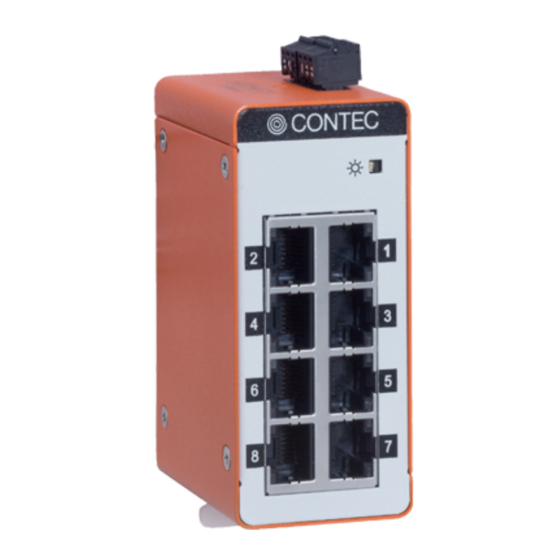
- Page 1 FLEXLAN 8 port 10/100M Unmanaged Industrial Switching HUB SH-8008F Manual CONTEC CO., LTD.
- Page 2 Product Configuration List Name Pcs. Unit Setup Guide Power Supply Connector Warranty Certificate Serial Number Label *The manual of this product can be downloaded from CONTEC website free of charge (https://www.contec.com/). Power Supply Connector Main Unit Setup Guide Warranty Certificate XXXXXXXXXXXXX...
-
Page 3: Copyright
All relevant issues have been considered in the preparation of this document. Should you notice an omission or any questionable item in this document, please feel free to notify CONTEC CO., LTD. Regardless of the foregoing statement, CONTEC assumes no responsibility for any errors that may appear in this document or for results obtained by the user as a result of using this product. -
Page 4: Table Of Contents
Table of Contents Check Your Package ..........................i Copyright ............................ii Trademarks ............................ii Table of Contents ..........................iii Before Using the Product About the Unit ............................ 5 Features ............................5 Customer Support ..........................6 Web Site ............................6 Limited One-Year Warranty ....................... 6 How to Obtain Service........................ - Page 5 Physical Dimensions ......................... 25 Differences from SH-8008(FIT)H ....................25 SH-8008F...
-
Page 6: Before Using The Product
1. Before Using the Product 1. Before Using the Product This chapter provides information you should know before using the product. About the Unit This product is a compact-sized industrial switching HUB [40(W) x 60(D) x 90(H)mm] with 8 ports for IEEE802.3u(100BASE-TX) / IEEE802.3(10BASE-T) compliant. In addition, the Auto MDI/MDI-X features automatic negotiation. -
Page 7: Customer Support
You can download updated driver software and differential files as well as sample programs available in several languages. Note! For product information Contact your retailer if you have any technical question about a CONTEC product or need its price, delivery time, or estimate information. Limited One-Year Warranty CONTEC products are warranted by CONTEC CO., LTD. -
Page 8: Safety Information
1. Before Using the Product Safety Information This document provides safety information using the following symbols to prevent accidents resulting in injury or death and the destruction of equipment and resources. Understand the meanings of these labels to operate the equipment safely. DANGER indicates an imminently hazardous situation which, if not avoided, will DANGER result in death or serious injury. - Page 9 Do not open the unit casing. CONTEC will disclaim any responsibility for equipment whose casing has been opened. Do not modify the unit. CONTEC will bear no responsibility for any problems, etc., resulting from modifying this unit. To clean this product, gently wipe it with a soft cloth soaked with water or a neutral detergent. Do not use benzene, a thinner, or other volatile solvents as they can cause the coating to discolor or peel off.
- Page 10 1. Before Using the Product Regardless of the foregoing statements, CONTEC is not liable for any damages whatsoever (including damages for loss of business profits) arising out of the use or inability to use this CONTEC product or the information contained herein.
-
Page 11: Environment
1. Before Using the Product Environment Use this product in the following environment. If used in an unauthorized environment, the product may overheat, malfunction, or cause a failure. Operating temperature -20 - 60°C Operating humidity 10 - 90%RH (No condensation) Corrosive gases None Floating dust particles... -
Page 12: Setup Of Hardware
2. Setup of Hardware 2. Setup of Hardware Mounting on or removing from DIN rail Before installing the product, you need to unlock the fixed hooks of the product. How to unlock fixed hooks -1 Stick a slotted screwdriver (the point should be smaller than 4.5mm) into a hole. Precision slotted screwdriver (point: 4.5mm or smaller) - Page 13 2. Setup of Hardware How to unlock fixed hooks -2 If your slotted screwdriver is not suitable for the hole. Place the slotted screwdriver (the point should be smaller than 8mm) as shown in the figure. Insert the slotted screwdriver (point: 8mm or smaller) into the position shown in the figure (between the casing and the arch of the fixed hook).
- Page 14 2. Setup of Hardware How to mount the product (1) Pull up/down the fixed hooks at the top/bottom to unlock. Figure 2.3. Mount the product on the DIN Rail < 1 / 3 > (2) Hang the product on the upper part of the DIN rail, and press it to the lower side of the DIN rail. Figure 2.3.
- Page 15 2. Setup of Hardware How to remove the product CAUTION Take off LAN cables and power cables connected to the product before removing from the DIN rail. Pull up/down the fixed hook at the top/bottom to unlock. Figure 2.4. Remove the product from the DIN Rail < 1 / 2 > (2) Pull the lower part of the product toward you and lift it up to remove.
-
Page 16: Installation Conditions
2. Setup of Hardware Installation Conditions WARNING Even within the temperature specification range, make sure the heat in the product can let off adequately in the case of high temperature environment application. Installation orientation Avoid installation on unsuitable installation directions as insufficient heat dissipation may occur. (Top) Suitable installation... -
Page 17: Spacing Between The System Unit And Any Surrounding Objects
2. Setup of Hardware Spacing between the system unit and any surrounding objects WARNING Do not locate the module in a fully enclosed housing. DIN rail mounted Secure a distance of at least 50mm between the top/bottom of the main product and any surrounding objects and also a distance of at least 50mm between each side of the product and any surrounding objects (5.8mm for the product overview level side). -
Page 18: Nomenclature Of Components And Their Settings
3. Nomenclature of Components and Their Settings 3. Nomenclature of Components and Their Settings Names of Components and Functions Figure 3.1 shows the nomenclature of components. Power supply connector POWER LED SPEED LED SPEED LED LINK/ACT LED LINK/ACT LED 10BASE-T/ 100BASE-TX port Figure 3.1. - Page 19 3. Nomenclature of Components and Their Settings Table 3.2. Connectors Name Function Power supply Acceptable connector: 15EDGK-3.5-03P-13-1000AH (DEGSON ELECTRONICS) Connector 15EDGK-3.5-03P-14-1000AH (DEGSON ELECTRONICS) The correspondence cable is AWG28-16. (Cable length should meet the specification of the power supply.) You can connect cables with screws. The product can function by one of the power connecters.
- Page 20 3. Nomenclature of Components and Their Settings About of Power Supply For power supply, use the power supply that rises within an input voltage range of 11.6VDC or higher within 50msec. The power supply that cannot meet this requirement may cause device failure or accident.
- Page 21 3. Nomenclature of Components and Their Settings SH-8008F...
-
Page 22: Connecting To A Network
4. Connecting to a Network 4. Connecting to a Network Network Cables Cables should meet the following specifications: 10BASE-T : Category 3 or greater UTP, STP cable 100m or less 100BASE-TX : Category 5 or greater UTP, STP cable 100m or less There are straight/crossover UTP and STP cables. -
Page 23: Connection Restrictions With 100Base-Tx Repeater Hubs
4. Connecting to a Network Connection Restrictions with 100BASE-TX Repeater HUBs At Class I, cascade connection with 100BASE-TX repeater HUBs is impossible. Up to two stages of cascade connection between 100BASE-TX Class II repeaters is possible. In addition, the total maximum cable length of cables (1)(2)(3) is 205m or less. -
Page 24: System Reference
5. System Reference 5. System Reference Specifications Table 5.1. Specifications Item Specifications Ethernet standards IEEE802.3/IEEE802.3u-compliant Data transfer rate 10Mbps/100Mbps (auto-negotiation) Access method CSMA/CD Communications method All ports: Full/Half duplex (auto-negotiation) Topology Star topology Flow control Full Duplex : IEEE802.3x compliant flow control Half Duplex :Back pressure Number of effective ports Switching method... - Page 25 5. System Reference Table 5.2. Installation Environment Requirements Item Specifications Operating temperature -20 - 60°C Storage temperature -20 - 60°C Humidity 10 - 90%RH(No condensation) Floating dust particles Not to be excessive Corrosive gases None Line-noise AC line/2kV, Signal line/1kV (JIS C61000-4-4Level 3, EN61000-4-4Level 3) Line-Noise Static electricity Contact discharge/4kV (JIS C61000-4-2Level 2, EN61000-4-2Level 2)
- Page 26 5. System Reference Physical Dimensions 12-24VDC [mm] Figure 5.1. Physical dimensions when Din rail fixation metal fittings (standard) are installed Differences from SH-8008(FIT)H The SH-8008F has the following differences from the conventional SH-8008(FIT)H : SH-8008(FIT)H SH-8008F Physical dimensions (mm) 52.4(W) x 64.7(D) x 94.0(H) 40(W) x 60(D) x 90(H) (exclusive of protrusions) (exclusive of protrusions)
- Page 27 April 2019 Edition 3-9-31, Himesato, Nishiyodogawa-ku, Osaka 555-0025, Japan https://www.contec.com/ No part of this document may be copied or reproduced in any form by any means without prior written consent of CONTEC CO., LTD. [04012019] [11102016] Management No. NA05201 [04012019_rev3] Parts No.
Need help?
Do you have a question about the FLEXLAN SH-8008F and is the answer not in the manual?
Questions and answers