Table of Contents
Advertisement
Quick Links
Advertisement
Table of Contents

Related Manuals for Velleman EtiamPro ECAMIP601


Summary of Contents for Velleman EtiamPro ECAMIP601
-
Page 2: Regulatory Information
ECAMIP601/ECAMIP601B·Quick Start Guide Regulatory Information FCC Information Please take attention that changes or modification not expressly approved by the party responsible for compliance could void the user’s authority to operate the equipment. FCC compliance: This equipment has been tested and found to comply with the limits for a Class B digital device, pursuant to part 15 of the FCC Rules. -
Page 3: Eu Conformity Statement
ECAMIP601/ECAMIP601B·Quick Start Guide 1. This device may not cause harmful interference. 2. This device must accept any interference received, including interference that may cause undesired operation. EU Conformity Statement This product and - if applicable - the supplied accessories too are marked with "CE" and comply therefore with the applicable harmonized European standards listed under the EMC Directive 2014/30/EU, the RoHS Directive 2011/65/EU. -
Page 4: Safety Instruction
ECAMIP601/ECAMIP601B·Quick Start Guide Safety Instruction These instructions are intended to ensure that user can use the product correctly to avoid danger or property loss. The precaution measure is divided into “Warnings” and “Cautions” Warnings: Serious injury or death may occur if any of the warnings are neglected. - Page 5 ECAMIP601/ECAMIP601B·Quick Start Guide ● In the use of the product, you must be in strict compliance with the electrical safety regulations of the nation and region. Please refer to technical specifications for detailed information. ● Input voltage should meet both the SELV (Safety Extra Low Voltage) and the Limited Power Source with 24 VAC or 12 VDC according to the IEC60950-1 standard.
- Page 6 ECAMIP601/ECAMIP601B·Quick Start Guide ● Do not aim the camera at the sun or extra bright places. Blooming or smearing may occur otherwise (which is not a malfunction) and affect the endurance of sensor at the same time. ● The sensor may be burned out by a laser beam, so when any laser equipment is in using, make sure that the surface of sensor will not be exposed to the laser beam.
- Page 7 ECAMIP601/ECAMIP601B·Quick Start Guide L’utilisation ou le remplacement inadéquats de la pile peuvent entraîner un risque d’explosion. Remplacez-la par le même type ou l’équivalent du même type seulement. Jetez les piles usagées conformément aux directives fournies par le fabricant de la pile. ●...
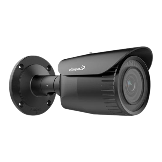
- Page 8 ECAMIP601/ECAMIP601B·Quick Start Guide 1 Appearance Overview of Type I Camera...
- Page 9 ECAMIP601/ECAMIP601B·Quick Start Guide Overview of Type II Camera Description Description Front Cover Sun Shield Lens IR LED Memory Card Slot Reset Button...
- Page 10 ECAMIP601/ECAMIP601B·Quick Start Guide Description Camera Body Bracket Network Interface Power Interface CVBS Interface Note: ● The item marked with the "*" is only supported by certain camera models. ● Press RESET about 10 s when the camera is powering on or rebooting to restore the default settings, including the username, password, IP address, port No., etc.
-
Page 11: Memory Card Installation
ECAMIP601/ECAMIP601B·Quick Start Guide 2 Installation Before you start: ● Make sure the device in the package is in good condition and all the assembly parts are included. ● The standard power supply is 12 VDC or PoE. Make sure your power supply matches with your camera. - Page 12 ECAMIP601/ECAMIP601B·Quick Start Guide Steps: 1. Loosen the lock screw to remove the sun shield. Lock Screw Remove the Sun Shield Figure 2-1 2. Rotate the front cover counterclockwise to remove it. Remove the Front Cover Figure 2-2 3. Insert the memory card into the memory card slot. Figure 2-3 Insert the Memory Card...
-
Page 13: Camera Mounting
ECAMIP601/ECAMIP601B·Quick Start Guide 4. Rotate the front cover clockwise back to the camera and replace the sun shield. 5. Tighten the lock screw clockwise to fix the sun shield. Fix the Front Cover Figure 2-4 2.2 Camera Mounting This series of cameras support the ceiling and wall mount. Different camera types share the similar installation steps, and we take type I camera as the example. - Page 14 ECAMIP601/ECAMIP601B·Quick Start Guide 8-Ø 5 mm Ø 100 mm Ceiling Mounting Ø 36 mm 1:Screw Hole for 2:Screw Hole for Bracket Mounting Base Drilling Holes in the Wall/Ceiling 3. If you need to route the cables through the wall (or the ceiling), dill a cable hole according to the drill template.
- Page 15 ECAMIP601/ECAMIP601B·Quick Start Guide Note: ● The supplied screw package contains self-tapping screws, and expansion bolts. ● For cement wall (or ceiling), use expansion bolts to secure the camera. For wooden wall (or ceiling), use self-tapping screws. 6. Connect the corresponding cables, such as power cord and network cable.
-
Page 16: Zoom And Focus Adjustment
ECAMIP601/ECAMIP601B·Quick Start Guide Rotation Adjustment Steps: 1). Loosen the lock screw 3. 2). Rotate the rotation position to adjust the azimuth angle of the image. The adjusting range is from 0° to 360°. 3). Tighten the lock screw 3. Rotation Pan: 0°... - Page 17 ECAMIP601/ECAMIP601B·Quick Start Guide Steps: 1. Remove the sun shield and front cover to expose the zoom lever and the focus lever. 2. View the camera image on the monitoring screen. 3. Loosen the zoom lever and move the lever between T (Tele) and W (Wide) to obtain the desired angle of view.
-
Page 18: Motor-Driven Lens
ECAMIP601/ECAMIP601B·Quick Start Guide 2.3.2 Motor-driven Lens Certain camera models of this series are equipped with a motor-driven lens. You can adjust the zoom and focus level on PTZ control panel by visiting the camera via web browser or client software. Zoom and Focus Adjustment via Web Browser 2.4 Waterproof Measures If the camera is installed outdoor, you should use the waterproof... - Page 19 ECAMIP601/ECAMIP601B·Quick Start Guide 2.4.1 Install Network Cable Waterproof Jacket Align Figure 2-10 Install Waterproof Jacket Steps: 1. Feed the network cable through ① and ③ in order. 2. Fix ② on the network cable between ① and ③. 3. Place ⑤ onto the end of ⑥ and plug the RJ45 male connector into RJ45 female connector.
- Page 20 ECAMIP601/ECAMIP601B·Quick Start Guide Waterproof Cables...
- Page 21 ECAMIP601/ECAMIP601B·Quick Start Guide 3 Set the Network Camera over the Note: You shall acknowledge that the use of the product with Internet access might be under network security risks. For avoidance of any network attacks and information leakage, please strengthen your own protection.
-
Page 22: Activate The Camera
ECAMIP601/ECAMIP601B·Quick Start Guide Network Camera Computer Connect via a Switch or a Router Figure 3-2 3.2 Activate the Camera You are required to activate the camera first by setting a strong password for it before you can use the camera. Activation via web browser, activation via SADP, and activation via client software are all supported. - Page 23 ECAMIP601/ECAMIP601B·Quick Start Guide Notes: The default IP address of the camera is 192.168.1.64. ⚫ The computer and the camera should belong to the same ⚫ subnet. For the camera enables the DHCP by default, you need to use ⚫ the SADP software to search the IP address. Activation Interface (Web) Figure 3-3 3.
- Page 24 ECAMIP601/ECAMIP601B·Quick Start Guide STRONG PASSWORD RECOMMENDED– We highly recommend you create a strong password of your own choosing (using a minimum of 8 characters, including upper case letters, lower case letters, numbers, and special characters) in order to increase the security of your product.
- Page 25 ECAMIP601/ECAMIP601B·Quick Start Guide Select inactive device. Input and confirm password. SADP Interface Figure 3-4 Note: The SADP software supports activating the camera in batch. Refer to the user manual of SADP software for details. 3. Create and input the new password in the password field and confirm the password.
-
Page 26: Modify The Ip Address
ECAMIP601/ECAMIP601B·Quick Start Guide Note: You can enable the Guarding Vision service for the device during activation. Refer to Chapter 5.1 for detailed information. 4. Click Activate to start activation. You can check whether the activation is completed on the popup window. - Page 27 ECAMIP601/ECAMIP601B·Quick Start Guide Modify the IP Address Figure 3-5 Note: You can enable the Guarding Vision service for the device during activation. Refer to Chapter 5.1 for detailed information. 4. Input the admin password and click Modify to activate your IP address modification.
-
Page 28: Access Via Web Browser
ECAMIP601/ECAMIP601B·Quick Start Guide 4 Access via Web Browser System Requirement: Operating System: Microsoft Windows XP SP1 and above version CPU: 2.0 GHz or higher RAM: 1G or higher Display: 1024×768 resolution or higher Web Browser: Internet Explorer 8.0 and above version, Apple Safari 5.0.2 and above version, Mozilla Firefox 5.0 and above version and Google Chrome 18 and above version Steps:... - Page 29 ECAMIP601/ECAMIP601B·Quick Start Guide 4. Click Login. Login Interface Figure 4-1 5. Install the plug-in before viewing the live video and managing the camera. Follow the installation prompts to install the plug-in. Note: You may have to close the web browser to finish the installation of the plug-in.
-
Page 30: Operate Via Guarding Vision App
ECAMIP601/ECAMIP601B·Quick Start Guide 5 Operate via Guarding Vision App Purpose: Guarding Vision is an application for mobile devices. With the App, you can view live image of the camera, receive alarm notification and so on. Note: Guarding Vision service is not supported by certain camera models. 5.1 Enable Guarding Vision Service on Camera Purpose: Guarding Vision service should be enabled on your camera before... - Page 31 ECAMIP601/ECAMIP601B·Quick Start Guide “Privacy Policy” Service” Verification Code Setting (SADP) Note: The verification code is required when you add the camera to Guarding Vision app. 3. Click and read "Terms of Service" and "Privacy Policy". 4. Confirm the settings. 5.1.2 Enable Guarding Vision Service via Web Browser Before you start: You need to activate the camera before enabling the service.
- Page 32 ECAMIP601/ECAMIP601B·Quick Start Guide Steps: 1. Access the camera through web browser. Refer to Chapter 4. 2. Enter platform access configuration interface: Configuration > Network > Advanced Settings > Platform Access. Guarding Vision dev.guardingvision.com Platform Access Configuration (Web) 3. Select Platform Access Mode as Guarding Vision. 4.
-
Page 33: Guarding Vision Setup
ECAMIP601/ECAMIP601B·Quick Start Guide Note: The verification code is required when you add the camera to Guarding Vision app. 7. Save the settings. 5.2 Guarding Vision Setup Steps: 1. Download and install the Guarding Vision app by searching “Guarding Vision” in App Store or Google Play 2. - Page 34 ECAMIP601/ECAMIP601B·Quick Start Guide Note: After the camera connects to the network, please wait one minute before any operation on the camera using Guarding Vision app. 2. In the Guarding Vision app, tap “+” on the upper-right corner and then scan the QR code of the camera to add the camera. You can find the QR code on the camera or on the cover of the Quick Start Guide of the camera in the package.
-
Page 35: Initialize The Memory Card
ECAMIP601/ECAMIP601B·Quick Start Guide Note: For detailed information, refer to the user manual of the Guarding Vision app. 5.4 Initialize the Memory Card Steps: Check the memory card status by tapping on the Storage Status in the Device Settings interface. If the memory card status displays as Uninitialized, tap to initialize it. - Page 36 Made in PRC Imported by Velleman Group nv Legen Heirweg 33, 9890 Gavere, Belgium www.velleman.eu...
Need help?
Do you have a question about the EtiamPro ECAMIP601 and is the answer not in the manual?
Questions and answers