
Subscribe to Our Youtube Channel
Related Manuals for Hoshizaki DBF-AS65WE-T


Summary of Contents for Hoshizaki DBF-AS65WE-T
- Page 1 DBF-AS65WE-T AUTOMATIC DRAFT BEER DISPENSER INSTRUCTION MANUAL 3-16 Minamiyakata, Sakae-cho, Toyoake, Aichi 470-1194 Japan L1B078101 (103119)
-
Page 2: Table Of Contents
IMPORTANT SAFETY INFORMATION ............................1 I. INSTALLATION INSTRUCTIONS .............................2 1. CONSTRUCTION ................................2 2. ACCESSORIES ...................................3 3. UNPACKING ..................................3 4. LOCATION ...................................4 5. INSTALLATION ..................................4 [a] DISPENSER..................................5 [b] DRAIN PAN ..................................5 [c] PLATFORM ADJUSTMENT ............................6 6. ELECTRICAL CONNECTIONS ............................8 7. GAS AND BEER CIRCUIT CONNECTIONS ........................8 [a] CO2 GAS CYLINDER ..............................8 [b] HOSE CONNECTIONS ..............................9 [c] CHECKS AFTER CONNECTIONS ..........................10... -
Page 3: Important Safety Information
ENGLISH IMPORTANT SAFETY INFORMATION Throughout this manual, notices appear to bring your attention to situations which could result in death, serious injury, or damage to the unit. WARNING Indicates a hazardous situation which, if not avoided, could result in death or serious injury. CAUTION Indicates a hazardous situation which, if not avoided, could result in minor or moderate injury. -
Page 4: Installation Instructions
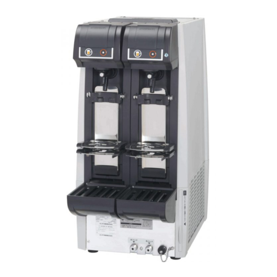
ENGLISH I. INSTALLATION INSTRUCTIONS 1. CONSTRUCTION Water Level Line (Label) Tank Cover Water Tank Operation Panel Panel Cover Operation Panel Unit Beer Tap Platform (Accessory) Air Filter Grille (Accessory) Drain Outlet Drain Pan (Accessory) Beer Inlet (Left) Beer Inlet (Right) Operation Panel Display Set Lamp... -
Page 5: Accessories
ENGLISH Prepare and install the following equipment. Consult with the liquor shop, beer company or distributor to prepare the regulator, keg coupler and CO2 gas cylinder designed for the beer to dispense. [1] CO2 Gas Cylinder [2] Regulator [3] Keg Coupler [4] Quick Beer Hose Joint (Coupler Side) [5] Quick Beer Hose Joint (Dispenser Side) [6] Quick Gas Hose Joint (Regulator Side) -
Page 6: Location
ENGLISH NOTICE Remove shipping carton, tape(s) and packing. If packing material is left in the dispenser, it will not work properly. To prevent damage, do not tilt the dispenser more than 45°. 1) After removing the packaging, make sure that the dispenser is in good condition. If in doubt, please do not use the dispenser but apply to professionally qualified personnel. -
Page 7: [A] Dispenser
ENGLISH [a] DISPENSER The front rubber feet can be moved backward from their original position. If the feet cannot fit within the installation space on the counter or table, use a screwdriver to remove the front feet from the bottom and refit at the following positions. Distance: A 274 mm Factory Setting Distance: B 388 mm Distance: a 244 mm After Adjustment Do not tilt more than 1 cm Distance: b 328 mm Distance: a... -
Page 8: [C] Platform Adjustment
ENGLISH [c] PLATFORM ADJUSTMENT The upper and lower platform positions are adjustable to accommodate two different mug heights. The guide can also be moved back and forth according to the mug shape. Mug Plate 1) The platform assembly has the components as shown on the right. Upper Platform Built-in Sensor Magnet Lower Platform Mark 2) Move the platform in the desired position and secure it with the screws. The upper platform position is adjustable between the 1st and 7th levels of the mug plate, and the lower platform position between the 4th and 12th levels. - Page 9 ENGLISH Position: A (Factory Setting) Upper Mounting Hole Bracket 1st Level Lower Mounting Position: B Hole Fit on boss 12th Level Platform Position Bracket Position Upper Platform Lower Platform Mug Plate Level Mounting Hole Mug Height (mm) Bracket Position Mounting Hole Mug Height (mm) Lower Upper...
-
Page 10: Electrical Connections
ENGLISH 6. ELECTRICAL CONNECTIONS WARNING THIS APPLIANCE MUST BE EARTHED This dispenser requires an earth that meets the national and local electrical code requirements. To prevent possible severe electrical shock to individuals or extensive damage to the unit, install a proper earth wire to the dispenser. Remove the plug from the mains socket before any maintenance, repairs or cleaning is undertaken. -
Page 11: [B] Hose Connections
ENGLISH [b] HOSE CONNECTIONS WARNING To prevent the risk of gas leaks and hose explosion, do not use any hoses other than specified by the beer company. Cut the hose end to have a vertical cutting plane and insert it securely into the quick hose joint to ensure a leak-free joint. NOTICE Do not reconnect the hoses without cutting them about 20 mm. Cut the hoses with a specialized tool such as hose cutter. -
Page 12: [C] Checks After Connections
ENGLISH [c] CHECKS AFTER CONNECTIONS 1) Wash the cleaning tank thoroughly and fill it with tap water. Note: If the cleaning tank is not clean, the beer circuit will be contaminated. 2) Turn the keg coupler clockwise to attach it to the cleaning tank. Note: Wash the joint between the keg coupler and cleaning tank if it is not clean. Rotary Type Vertical Type 3) Lift up and remove the platform. -
Page 13: Sold Out Sensor Setting
ENGLISH * After 8 to 13 hours (depending on ambient/water temperature), open the top cover and check that ice is stored in the water tank. 5) Instruct the user on how to operate the unit. 6) Hand this instruction manual to the user. 9. -
Page 14: Operating Instructions
ENGLISH Reset frequency for number of mugs Number of keg * Keg replacement is counted every time the number of kegs is reset by the replacements 0 - 9999 stop button operation. (reset frequency) * To reset, press and hold the stop button for 3 seconds. Dispense lamp Adjustment of dispense lamp brightness 1 - 8... -
Page 15: [B] Cooling Water Supply
ENGLISH Above 300 μS/cm: Excessive ice may build up on evaporator and freeze beer inside beer coil preventing beer from being dispensed properly. Nozzle Cap How to make cooling water with 100-300 μS/cm of E.C. The capacity of the water tank of this unit is approx. 30 L. Make the cooling water by dissolving 5 g of pure baking soda in approx. -
Page 16: [C] Checking Beer Keg
ENGLISH 5) Check the regulator gasket. If it is damaged or not provided, install a new gasket. (Contact the liquor shop, beer company or distributor.) 6) Install the regulator securely on the CO2 gas cylinder. NOTICE Tighten the nut by hand first, then with the spanner (accessory) so that the level gauge will be upright. 7) Open the main valve by turning it counterclockwise, and check the regulator nut for gas leak (sound). If gas is leaking, the nut must be loose or the gasket must be damaged or not provided. -
Page 17: Start Up
ENGLISH 2) Turn the regulator adjust dial to set the pressure to “0” (MPa). 3) Turn the keg coupler counterclockwise to remove it from the beer keg. Rotary Type Vertical Type 4) Turn the keg coupler clockwise to attach it to the new beer keg. Note: Wash the joint between the keg coupler and beer keg if it is not clean. -
Page 18: Setting Liquid And Foam Amounts
ENGLISH 4) Press and hold the foam button to purge air out of the beer circuit through the foam nozzle. Release the foam button when no more air is purged and a steady flow of foam is obtained. When beer reaches the sold out sensor, the sold out lamp goes off and the ready lamp comes on. 5) Press the liquid button to check that clear beer is dispensed. Release the liquid button to stop beer. IMPORTANT If the liquid nozzle is used to purge air out of the beer circuit, liquid will splash out together with gas. -
Page 19: Dispensing
ENGLISH 6. DISPENSING [a] AUTOMATIC DISPENSING 1) Check that the beer tap is not dripping. Place a clean mug on the same platform as used for the setting. 2) Press the dispense button. The unit automatically dispenses the set amount of liquid and foam. -
Page 20: [D] Switching To Automatic Dispensing Mode
ENGLISH 3) To dispense foam, push the beer tap lever quickly away from you until it stops. To avoid liquid foam, do not stop the lever halfway. Release the lever Valve Shaft End to stop foam. Note: When the beer tap lever is pushed during manual dispensing operation, the valve shaft end comes out. -
Page 21: Shut Down
ENGLISH 5) Wipe off moisture from the end of the beer tap nozzles. Clean and attach the nozzle caps (accessory). Note: Always attach the accessory nozzle caps at the end of dispensing operation or during periods of non-use to prevent entrance of insects or dirt into the beer tap nozzles. 9. SHUT DOWN [a] SHUT DOWN 1) Check that the keg coupler is closed. See “8. END OF DISPENSING OPERATION”. Note: If the keg coupler is open, the floor can be wet in the event of beer leakage. -
Page 22: Basic Cleaning
ENGLISH 1. BASIC CLEANING 1) Wash your hands. 2) Prepare clean cloths. 3) Unplug the unit. 4) Mix about 10 mL of 10% invert soap (benzalkonium chloride) solution in 1 L of warm water (30 to 40°C). Damp a dry cloth to wipe the parts clean. - Page 23 ENGLISH 12) Open the beer circuit. Rotary type: Turn the keg coupler handle clockwise until it stops. Vertical type: Push down the keg coupler handle until it locks in place. Note: If the cleaning tank is provided with a siphon tube, lay the cleaning tank with the ferrule at the top. If not, lay the cleaning tank with the ferrule at the bottom.
-
Page 24: Drain Pan And Grille (Daily)
ENGLISH 3. DRAIN PAN AND GRILLE (DAILY) 1) Lift up the front of the drain pan and pull it off toward you. Note: Be careful not to spill water and beer in the drain pan. 2) Wash the grille and drain pan with tap water. Grille (2) Pull off 3) Set the grille on the drain pan and fit the drain pan by pushing it securely into the drain pan support,. - Page 25 ENGLISH 8) Turn the keg coupler counterclockwise to remove it from the beer keg. Rotary Type Vertical Type 9) Remove the quick beer hose joint from the keg coupler, and put only one cleaning Quick Beer Hose Joint sponge (accessory) into the joint. Cleaning Sponge NOTICE Use of more than one cleaning sponge or a non-accessory sponge can cause...
-
Page 26: Disassembly And Cleaning Of Beer Tap (Weekly)
ENGLISH 21) Turn the keg coupler counterclockwise to remove it from the cleaning tank. 22) Thoroughly wash and dry the cleaning sponge and store it for later use. 23) Repeat the above steps 9) to 22) until clear water comes out of the beer tap. Note: Receive the water in a mug or glass to check its clearness. -
Page 27: Keg Coupler (Weekly)
ENGLISH 6) Use the accessory brush (S) to clean the two small holes in the beer tap. Brush (S) 7) Rinse the parts thoroughly with tap water. 8) Fit the valve shaft in the original (normal) direction while aligning the holes in the beer tap and valve shaft (larger hole facing up), and tighten the cap nut. -
Page 28: Inspection
ENGLISH IV. INSPECTION 1. COOLING WATER AND ELECTRODE (BIANNUALLY) IMPORTANT Replace the cooling water and check the electrode for cleanliness twice a year. Water Tank 1) Unplug the unit. The refrigeration unit and agitator motor stop. 2) Remove the top cover. 3) Check that the water level is above the water level mark inside the water tank. -
Page 29: Other Information
ENGLISH V. OTHER INFORMATION 1. PREPARING THE DISPENSER FOR LONG STORAGE WARNING When shutting down the dispenser for more than a week, unplug the unit. 1) Drain the water tank according to “II. 9. [b] DRAINING WATER TANK”. 2) Carry out the following maintenance procedures to clean and drain the beer circuit and to keep the unit clean: III. -
Page 30: Relocation, Disposal, Transfer
4. WARRANTY Hoshizaki warrants to the original owner/user that all Hoshizaki branded products shall be free of defects in material and/or workmanship for the duration of the “warranty period”. The warranty shall be effective for one year from the date of installation. Hoshizaki’s liability under the terms of the warranty are limited and shall exclude routine servicing, cleaning, essential maintenance and/or repairs occasioned by misuse and installations not in accordance with Hoshizaki guidelines. -
Page 31: Specifications
ENGLISH SPECIFICATIONS Model DBF-AS65WE-T Power Supply 1 phase 220V 50/60Hz Capacity: 0.52kVA (2.4A) Electric Consumption Motor: 285 / 345W Ice Making Time 10 hrs (ambient temp 30°C, initial cooling water temp 25°C) Dispensing Capacity 65 L (30°C to 8°C / 4 hrs)
Need help?
Do you have a question about the DBF-AS65WE-T and is the answer not in the manual?
Questions and answers