
Related Manuals for Sartorius Arium H2O-ARST-P-B


Summary of Contents for Sartorius Arium H2O-ARST-P-B
- Page 1 Operating Instructions Original Operating Instructions Arium Smart Station ® H2O-ARST-P-B | H2O-ARST-P-T | H2O-ARST-UP-B | H2O-ARST-UP-T Dispensing Unit 1000084125...
-
Page 3: Table Of Contents
Contents Contents 1 About these Instructions . . . . . . . . . . . . . . . . . . . . . . . . . . . 5 4.8 Buttons in the Operating Display. - Page 4 16 Sartorius Service . . . . . . . . . . . . . . . . . . .
-
Page 5: About These Instructions
About these Instructions About these Instructions Scope These instructions are part of the device. These instructions apply to the device in the following versions: Device Model Dispensing unit as benchtop version for H2O-ARST-UP-T ultrapure water, “Ultrapure” version (type 1) Dispensing unit as benchtop version for pure H2O-ARST-P-T water, “Pure”... -
Page 6: Symbols Used
About these Instructions Symbols Used 1.4.1 Warnings in Operation Descriptions WARNING Denotes a hazard that may result in death or severe injury if it is not avoided. CAUTION Denotes a danger with risk that moderate or minor injury may result if it is not avoided. -
Page 7: Safety Information
We recommend that any repair work, even that not covered by the warranty, is carried out by Sartorius Service or after consulting Sartorius Service. Only the maintenance tasks described in these instructions should be carried out. For maintenance tasks that need to be carried out by Sartorius Service, contact Sartorius Service. Arium Smart Station Operating Instructions ®... -
Page 8: Foreseeable Misuse
Retain the instructions. If these instructions are lost, request a replacement or download the latest version from the Sartorius website (www.sartorius.com). Device Functionality A damaged device or worn-out parts can cause malfunctions or lead to hard-to-detect hazards. -
Page 9: Safety Information On The Device
Only use the original power supply unit and original power supply cable. If the power supply unit or power supply cable must be replaced: Please contact Sartorius Service. Do not repair or modify the power supply unit or power supply cable. -
Page 10: Device Description
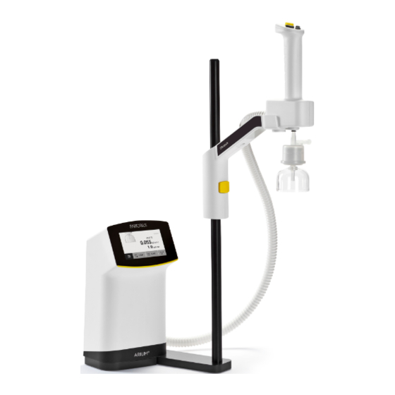
Device Description Device Description Device Overview Fig. 1: Dispensing unit with stand (example) Pos . Name Description Hand-held Part Controls the dispensing of water. Stand arm Holds the hand-held part. Adjustment button Used to set the height for the hand-held part. Protective tubing Used to protect the water tubes and the data cable. -
Page 11: Hand-Held Part
Device Description Hand-held Part Fig. 2: Hand-held part of the dispensing unit Pos . Name Description [Start / stop] button − If the key is briefly pressed: Starts or stops the dispensing. − If the button is held down: Manual dispensing. −... -
Page 12: Water Connections And Clips
Device Description Water Connections and Clips Fig. 3: Water connections and clip (example) Pos . Name Description Mounting hole Clips are attached. “Outlet” connection For “Ultrapure” version only: Used to connect the outlet tube to an Arium ® water treatment device or to the connection of another Arium Smart ®... -
Page 13: Electrical Connections
Device Description Electrical Connections Fig. 4: Electrical connections (example) Pos . Name Description Hand-held part connection Used to connect the hand-held part to the control unit. Ethernet “A” Used to connect an Arium water treatment device or another Arium ® ®... -
Page 14: Models H2O-Arst-Up-B, H2O-Arst-P-B: Wall Brackets For The Dispensing Unit
Device Description Models H2O-ARST-UP-B, H2O-ARST-P-B: Wall Brackets for the Dispensing Unit Fig. 5: Wall brackets for the dispensing unit (example) Pos . Name Description Wall bracket for hand-held part Used to hold the hand-held part. Clip Secures the protective tubing. Wall bracket for the control unit Used to hold the control unit. -
Page 15: Power Supply Unit And Wall Bracket
Device Description Power Supply Unit and Wall Bracket Fig. 6: Power supply unit and wall bracket (example) Pos . Name Description Power supply unit Used to supply power to the device. Power supply cable Has a country-specific plug type. Wall bracket for power supply unit Secures the power supply unit horizontally or vertically to a wall. -
Page 16: Ultrapure" Version: Serial Connection Of
Device Description “Ultrapure” Version: Serial Connection of Several Dispensing Units 3.7.1 System Setup Fig. 7: System setup with up to three dispensing units (example) Pos . Name Description Arium water treatment device Supplies the ultrapure water to the dispensing units. ®... -
Page 17: Operating Design
Operating Design Operating Design “Ultrapure” Version: Operating Elements in Dispensing Mode In dispensing mode, the display shows information from the connected Arium water treatment device, as well as the ® buttons relevant for dispensing. Fig. 8: Dispensing mode of the dispensing unit for ultrapure water (schematic representation) Pos . -
Page 18: Pure" Version: Operating Elements In
Operating Design Flow speed − Indicates the level of the current flow speed using the number of colored droplets. − [-] and [+] symbols: Indicate that the flow speed can be increased or reduced using the [Plus] and [Minus] buttons on the hand-held part. −... -
Page 19: Menu
Operating Design Menu 4.3.1 “User” Role (Without PIN Protection) All system settings and work steps for dispensing can be carried out in the menu. Dispensing Care Fig. 10: Menu for the “User” role (example) Pos . Symbol Name Description Dispensing Opens the dispensing mode. -
Page 20: Administrator" Role
Operating Design 4.3.2 “Administrator” Role All system settings and work steps for the maintenance of the device can be carried out in the menu. Administrator Arium Smart Station 1 Dispensing Care Fig. 11: Menu for the “Administrator” role (example) Pos . Symbol Name Description... -
Page 21: Messages In Dispensing Mode
Operating Design Messages in Dispensing Mode If several messages are active, the message list can be called up in the dispensing mode (see Chapter “4.5 Message List”, page 22). The message list only appears when several messages are active and at least one message cannot be displayed in the operating display for the conductivity or temperature of the water. -
Page 22: Message List
Operating Design Message List All active messages can be viewed in the message list. The cause of the message does not necessarily lie with the dispensing unit, but usually with the connected Arium water treatment device. ® The messages in the message list are sorted according to priority. Error messages appear first in the list. -
Page 23: Numeric Keypad
Operating Design Numeric Keypad The numeric keypad is used to enter a dispensing volume or various system settings. START Volume Liter Fig. 14: Numeric keypad (example: entering the volume) Pos . Name Description Name of the dialog box Displays the name of the current dialog box. Numerical value Displays the currently entered numeric value. -
Page 24: Buttons In The Operating Display
Operating Design Buttons in the Operating Display 4.8.1 Buttons for Operation and Navigation in Displays Symbol Name Description [Menu] button Opens the main menu. [Standby] button − In standby mode: Switches the device on. − In switched-on state: Switches the device into standby mode. -
Page 25: Buttons For Editing Or Managing
Operating Design 4.8.2 Buttons for Editing or Managing Entries Symbol Name Description [Save] button − Saves a selection or entry. − Opens a previously selected menu item [OK] button Confirms the current display and initializes the next step. [More] button Displays additional functions and navigation options in a display. -
Page 26: Navigating Menus
Operating Design Navigating Menus Procedure To open a menu: Tap on the desired menu button in the function bar or on a symbol. The menu will open. The name of the open menu is displayed in the navigation bar. To return to the main menu from other displays: Press the [Menu] button or press the [Back] button (multiple times) until the main menu is displayed. -
Page 27: Menu Structure
Displays the data for the next required replacement of all consumables in the entire system. Service information Service contact Displays the responsible contact at Sartorius Service. Next maintenance Displays the date for the next scheduled maintenance. Display temperature If the conductivity value is compensated: Activates the water temperature display. -
Page 28: Parameter List
Operating Design Level 1 Level 2 Level 3 Description Display brightness Changes the brightness of the operating display. Settings Reset settings Resets the dispensing unit to the default settings, e.g., temperature display. Admin Opens the defined role for the administrator or service. Service Role management... -
Page 29: Parameters In The "Settings | Display Temperature" Menu
Displays the data for the next required replacement of all consumables in the entire system. Service Service contact Displays the responsible contact at Sartorius Service. information Next maintenance If a service interval is activated: Displays the date for the next... -
Page 30: Parameters In The "Settings | Acoustic Signals" Menu
Operating Design 4.11.5 Parameters in the “Settings | Acoustic Signals” Menu Parameter Setting Values Explanation Display button Activates acoustic signals when pressing a button. signals Off* Deactivates acoustic signals when pressing a button. Key signals on Activates acoustic signals when pressing the hand-held part hand-held keys [Plus], [Minus] and [Volume]. -
Page 31: Parameters In The "Role
Operating Design 4.11.8 Parameters in the “Role Management” Menu Parameter Setting Values Explanation Roles Administrator − Opens the defined role for the administrator and service. − Assigns appropriate rights for operating the device to each Service role. − The device functions that can be used depend on the rights of the user role. -
Page 32: Installation
Installation Installation Scope of Delivery Item Quantity Control unit For “Ultrapure” version only: Hand-held part with dispense tube including inlet and outlet water tube, ¼” outer diameter, data cable For “Pure” version only: Hand-held part with dispense tube including inlet water tube, ¼” outer diameter, data cable For “Ultrapure”... -
Page 33: Selecting An Installation Site
Installation Selecting an Installation Site Procedure Make sure that the following conditions are met at the installation site: Condition Requirements Ambient conditions − Suitability tested (for ambient conditions see Chapter “14.3 Ambient Conditions”, page 69). Footprint or installation − Stable, even surface or vertical space installation space, e.g., a sink −... -
Page 34: Unpacking And Installing The Device
Lift the device by the stand support rod and the control unit at the same time. We recommend that installation and commissioning of the device should be carried out by Sartorius Service. Procedure Please contact Sartorius Service. We recommend keeping the original packaging in case the device needs to be returned or repaired, e.g., for repairs. -
Page 35: Installing The Stand Arm
Installation Place the control unit on its side. Unscrew the four screws (1) including the three bases on the underside of the control unit. Remove the stand base and the base plate. Rotate the base plate 180° and place the stand arm on the left-hand side of the control unit. -
Page 36: Installing The Wall Bracket For The Power
Installation Installing the Wall Bracket for the Power Supply Unit The wall bracket can be secured to a wall using an adhesive tape or screws. 5.6.1 Securing Wall Bracket with the Adhesive Tapes Procedure CAUTION Danger of injury if the wall bracket is not installed correctly! People could be injured if the power supply unit falls down. -
Page 37: Dispensing Unit With Wall Bracket: Installing Wall Bracket For The Control Unit
Installation Dispensing Unit with Wall Bracket: Installing Wall Bracket for the Control Unit Procedure CAUTION Danger of injury if the wall bracket is not installed correctly! People could be injured if the device falls down. Fasten the wall bracket securely to the wall. NOTICE The device may be destroyed if it falls down! Fasten the wall bracket securely to the wall. -
Page 38: Dispensing Unit With Wall Bracket: Installing The Wall Bracket For The Hand-Held Part
Installation Dispensing Unit with Wall Bracket: Installing the Wall Bracket for the Hand-held Part Procedure CAUTION Danger of injury if the wall bracket is not installed correctly! People could be injured if the device falls down. Fasten the wall bracket securely to the wall. -
Page 39: Getting Started
NOTICE Risk of device damage or malfunction due to unsuitable or damaged tubing! The use of tubing or accessories that are not approved by Sartorius may lead to leakage or damage to the device. Use only original Sartorius tubing. Do not bend the tubing. -
Page 40: For "Ultrapure" Version: Establishing Serial Water Circulation System For Up To Three Dispensing Units
Supplies the ultrapure water to the dispensing units. ® We recommend that the connection of several dispensing units should be set up by Sartorius Service. Water outlet on the Arium water treatment device: When using the dispensing units, the water flow is reduced. - Page 41 Getting Started Configuring Connection Tube 1 Required tools: Tubing release tool Procedure Loosen the unmarked angle joint (1) using the tubing release tool and remove. Configuring Connection Tube 2 Required tools: Tubing release tool, scissors Procedure On the straight connector (2), cut open the two black safety clips (3) on the side using the scissors and remove from the connection.
- Page 42 Getting Started Connecting Dispensing Unit 1 to Dispensing Unit 2 Procedure Connect the black marked connection tube 2 of the second protective tubing to the black marked “Inlet” (1) connection of dispensing unit 2. Connect the other side of this tube to the unmarked water outlet (1) of dispensing unit 1.
-
Page 43: For "Pure" Version: Connecting The Dispensing Unit To The Arium ® Bagtank
NOTICE Risk of device damage or malfunction due to unsuitable or damaged tubing! The use of tubing or accessories that are not approved by Sartorius may lead to leakage or damage to the device. Use only original Sartorius tubing. Do not bend the tubing. -
Page 44: For "Pure" Version: Connecting Dispense Tube Of The Hand-Held Part
Getting Started 6.1.4 For “Pure” Version: Connecting Dispense Tube of the Hand-held Part Procedure Connect the blue marked inlet water tube of the hand-held part to the identically marked connector (1). 6.1.5 For “Ultrapure” Version: Connecting Dispense Tubes of the Hand-held Part Procedure Connect the colored marked inlet and outlet water tubes of the hand- held part to the identically marked connectors (1). -
Page 45: Installing The Hand-Held Part
Getting Started 6.1.8 Installing the Hand-held Part Procedure Place the hand-held part (1) into the stand arm (2) or the wall bracket. The hand-held part (1) is held in the stand arm or the wall bracket magnetically. 6.1.9 Connecting the Ethernet System Cable Procedure Connect the Ethernet system cable to one of the two connectors (1) on the dispensing unit. -
Page 46: Securing Protective Tubing
Getting Started 6.1.11 Securing Protective Tubing Procedure Secure the protective tubing (1) in the clip (2) by applying pressure. The clip closes, engages, and secures the protective tubing. Connecting the Power Supply Unit WARNING Danger of electric shock due to incorrect handling of power cables! Severe injuries caused by using defective power supply cables. - Page 47 If the input voltage is too high: Do not connect the device to the power supply. Only use the original Sartorius power supply unit. Check whether the plug design of the power cable complies with your country’s standard.
-
Page 48: Connecting The Final Filter (Optional)
Getting Started Connecting the Final Filter (Optional) Requirements The “Connect filter” dialog box is displayed in the operating display. Procedure Press the final filter (1) into the quick connector of the water outlet. Confirm the connection of the final filter with the [OK] button. The display changes to the dispensing screen. -
Page 49: Operation
Operation Operation Switching the Device On and Off Procedure To switch the device on: Connect the device to the power supply. The device starts and performs a system check. To switch the device off: Disconnect the power cable from the power supply. -
Page 50: Dispensing Water Manually
Operation Procedure If dispensing is going to take place via the final filter: Remove the protective cap on the bell assembly of the final filter. If dispensing is going to take place via the dispense tube: Remove the final filter (see Chapter 8.4.1, page 59). Connect a dispense tube. -
Page 51: Dispensing Water With Volume-Control
Operation To start with minimum flow speed: Press the [Plus] button (1). The dispensing starts. The volume previously dispensed (1) is displayed. For “Ultrapure” version only: The [Plus] and [Minus] buttons can be used to change the flow speed during dispensing. When the dispensing is complete: Attach the protective cap to the bell assembly of the final filter. - Page 52 Operation Procedure NOTICE Equipment may be damaged by objects with points or sharp edges! Do not exert mechanical pressure on the operating display with sharp objects. The operating element should only be operated by lightly pressing it using the tips of your fingers. The operating elements can also be operated with laboratory gloves.
- Page 53 Operation To cancel the dispensing prematurely: Press the [Cancel] button (1). Selecting a Saved Volume Value The device saves values for the following volumes: − The last volume dispensed (not manual dispensing). − Saved favorite volumes. Requirements The device is in dispensing mode and is ready for dispensing. Procedure To start a dispensing process with the last dispensed or the saved favorite volume: Press the [Volume] button (1).
-
Page 54: Confirming Dispensing Cancellation
Operation Repeating the Last Volume-controlled Dispensing Release several volume-controlled dispensing processes each with the same volume in a sequence. Requirements The hand-held part has been held in the hand since the last volume- controlled dispensing process. Procedure To start another dispensing process with the last volume dispensed: Press the [Start / Stop] button on the hand-held part or press the [START] button (1). -
Page 55: Opening The Menu
Operation Opening the Menu Procedure To open the menu: In dispensing mode, press the [Menu] button. The following tasks can be performed: Possible Work on the Device Chapter, Page Activating or deactivating standby mode 7.4, 55 Changing system settings 4.11, 28 Opening the “Care”... -
Page 56: Changing System Settings
Operation To deactivate standby mode: Press the [Standby] button (1). The start screen appears. Once the system start is complete, the display changes to the dispensing screen. Changing System Settings The system settings for the device, e.g., for the flow rate, can be changed in the “Settings”... -
Page 57: Cleaning And Maintenance
Cleaning and Maintenance Cleaning and Maintenance Cleaning 8.1.1 Cleaning the Operating Display Requirements The operating process has been completed. Procedure To avoid uncontrolled changes to the device settings: Activate standby mode (see Chapter “7.4 Activating or Deactivating Standby Mode”, page 55). Wipe the operating display gently with a soft, dry cloth. -
Page 58: Maintenance Schedule
Cleaning and Maintenance Maintenance Schedule Depending on the volume of water dispensed, it may be necessary to change the consumables more often than specified in the maintenance schedule. If, for example, sterile water is always required, the final filter must be replaced regularly. -
Page 59: Changing The Final Filter
Cleaning and Maintenance Changing the Final Filter 8.4.1 Removing the Final Filter Requirements − If the menu item [Sterile filter] or [Ultrafilter] is activated in the “Replace consumables” menu: The “Remove filter” dialog box appears. Remove filter Remove the final filter. Required tools: Tubing release tool Procedure Use the tubing release tool (1) to push and hold the water outlet quick... -
Page 60: Performing Venting
Cleaning and Maintenance Performing Venting During the venting process, air is removed from the water circulation. The water circulation must be rinsed if the following conditions are present: − The displayed water quality fluctuates continuously during operation. − The device has been out of operation for an extended period. Procedure Press the [Venting] menu item in the “Care”... -
Page 61: Pure" Version: Perform Depressurization
Cleaning and Maintenance “Pure” Version: Perform Depressurization The device is pressurized during operation. If the device is taken out of operation for an extended period or permanently, the pressure in the device must be released. Procedure Press the [Depressurize] menu item in the “Care” menu. The “Remove filter”... -
Page 62: Enabling, Disabling, Or Configuring Reminders
Cleaning and Maintenance When depressurization is complete, the “Turn off device” dialog box appears. Switching the device Disconnect the device from the power supply. Pressurization is carried out when the device is switched on again. Disconnect the device from the power supply. -
Page 63: Faults
Changing the replaced. filter has expired. Final Filter”, page 59 Maintenance by The maintenance Please contact Sartorius Service. Sartorius Service is maintenance service interval has required. service must expired. conducted. Error Messages If an error message is active on the Arium water treatment device, dispensing is canceled and locked automatically. -
Page 64: Other Faults
Replace the final filter. 8.4, 59 If no water can be dispensed when the final filter has been removed: Please contact Sartorius Service. “Standby” not A device in the system is not in the Ensure that all the devices in the possible. -
Page 65: Decommissioning
Decommissioning 10 Decommissioning 10.1 Decommissioning Requirements The operating process has been completed. Procedure Finish the water dispensing (see Chapter “8.6 “Pure” Version: Perform Depressurization”, page 61) Disconnect the device from the power supply. Disconnect the device from the supply lines. Remove all consumables used. Disconnect all connected components from the device. -
Page 66: Storage And Shipping
Defective devices or parts can be returned to Sartorius. Returned devices must be clean, decontaminated, and properly packed. Transport damage as well as measures for subsequent cleaning and disinfection of the device or parts by Sartorius shall be charged to sender. Procedure Decommission the device. -
Page 67: Disposal
The device has been decontaminated. Procedure Dispose of the device. Follow the disposal instructions on our website (www.sartorius.com). Inform the disposal facility that there is a lithium button cell battery, type CR2032, installed inside the device. Dispose of the packaging and consumables in accordance with local government regulations. -
Page 68: Technical Data
Technical Data 14 Technical Data 14.1 Dimensions and Weights 14.1.1 Dispensing Unit with Stand Unit Value Dimensions Control unit with stand (L × W × H) 213 × 213 × 598 Maximum operating range of the stand arm (L × W × H) 428 × 476 × 835 Tube length Distance from water treatment device, approx. -
Page 69: Ambient Conditions
Relative air humidity, maximum 14.5 Electrical Data 14.5.1 Power Supply to the Power Supply Unit Unit Value Power supply only permitted using the Sartorius power supply unit Sartorius power supply unit, part no. 1000081531 Primary AC voltage 100–240 (± 10%) Frequency 50–60 (±... -
Page 70: Dispensing Unit
Technical Data Unit Value Protection class according to IEC 62368-1 Power supply cable Power supply cable according to IEC 60320-1 / C14: Country-specific, 3-pin, two-sided plug For further data, see label on the power supply unit 14.5.2 Power Consumption of the Dispensing Unit Unit Value Power consumption, typical... -
Page 71: Interfaces
10 / 100 14.7.2 Specifications for the USB-C Interface Unit Value Communication: USB host (master) Connectable devices Sartorius printer USB stick, maximum storage size Full- / Low-Speed, 5 V / 500 mA 14.8 Permitted Devices or Components Arium water treatment devices: Arium Pro, ®... -
Page 72: Information On Disposal
− Deactivate any unused IT connections Dealing with IT security incidents − React to IT security incidents immediately. Contact Sartorius Service if you have any questions. Training users on IT security measures − Inform users about the IT security measures taken, e.g., for handling passwords or IT security incidents. -
Page 73: Accessories And Consumables
H2O-CUF ® 16 Sartorius Service Sartorius Service is at your disposal for queries regarding the device. Please visit the Sartorius website (www.sartorius.com) for information about the service addresses, services provided, or to contact a local representative. When contacting Sartorius Service with questions about the system or in the event of malfunctions, be sure to have the device information, e.g., serial... - Page 74 Conformity Documents Arium Smart Station Operating Instructions ®...
- Page 75 Conformity Documents Arium Smart Station Operating Instructions ®...
- Page 76 Sartorius Lab Instruments GmbH & Co. KG Otto-Brenner-Strasse 20 37079 Goettingen, Germany Phone: +49 551 308 0 www.sartorius.com The information and figures contained in these instructions correspond to the version date specified below. Sartorius reserves the right to make changes to the technology, features, specifications and design of the equipment without notice.
Need help?
Do you have a question about the Arium H2O-ARST-P-B and is the answer not in the manual?
Questions and answers