Advertisement
Quick Links
Advertisement

Related Manuals for CPS CARSMART CSA134


Summary of Contents for CPS CARSMART CSA134
- Page 1 CARSMART– AUTOMATIC A/C SERVICE UNIT MODEL CSA134 / CSA1234 USER AND OPERATIONS MANUAL VER1.0...
-
Page 2: General Info
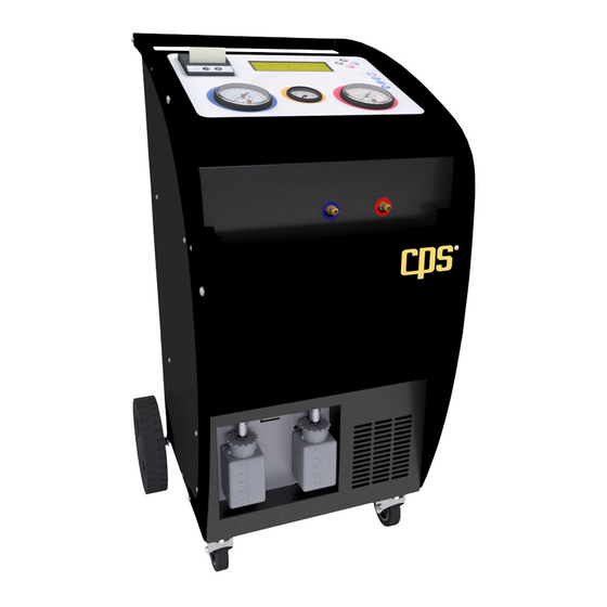
INDEX CARSMART – FULLY AUTOMATIC A/C SERVICE UNIT MODEL CSA134 / CSA1234 USER AND OPERATIONS MANUAL PARAGRAPH INDEX ARAGRAPH TITLE ESCRIPTION ERSION AGE N ENERAL RELIMINARY INSTRUCTIONS PROPER USE NSTALLATION REPARING FOR USE NIT DESCRIPTION OMPONENTS DESCRIPTION USE OF BUTTONS AIN MENU DESCRIPTION AIN MENU AND MAIN WORKING CYCLES SE WITH... - Page 3 GENERAL INFO INTRODUCTION The CPS CSA CarSmart Series Refrigerant Management System is designed with ease of use for the technician in mind. It has an icon-based touch screen display, a comprehensive vehicle data base as well as the ability to set up to 30 custom vehicle data per machine.
- Page 4 GENERAL INFO • CAUTION- Use only CPS certified hose assemblies on this unit. The hose assemblies are made to proper length, contain shut offs where required and have direct effect on the proper operation of this equipment. • Do not smoke whilst using the recharging unit.
- Page 5 INSTALLATION Installation and preparing for use Unpacking and checking of the unit Check the integrity of the packaging to exclude damages occurred during transport. Check the entirety of the equipment and of the relevant accessories. Non conformities, if any, have to be pointed out immediately and written on the transport documents.
- Page 6 INSTALLATION PPLIES TO The vacuum and the following leak test should be repeated whenever the charging hoses Could have been contaminated with air. Check if the setting relevant to the length of the hoses is correct (select “OPTIONS AND SETTINGS” then “HOSE LENGTH”...
- Page 7 UNIT DESCRIPTION Component’s description, use of buttons Preliminary test Connect the feeding cable to the mains (220V AC single phase) and turn on the main switch. Check that the refrigerant used by the A/C system to be serviced is the one the service unit is intended for: R134a or R1234YF Check oil levels (vacuum pump and new oil reservoir).
- Page 8 UNIT DESCRIPTION Re.: Description Note High Pressure Gauge For the inspection and diagnosis of the A/C system Tank Pressure Gauge To check the pressure inside the gas storage reservoir. For the inspection and diagnosis of the A/C system and for Low Pressure Gauge the control of the vacuum.
- Page 9 MENU DESCRIPTION Main menu and main working cycle description After switching on the unit displays the SW version and performs an automatic test to check if there are any gas leaks in the machine and, eventually, stops the operation. Switch on the unit which will display Firmware version and refrigerant type The unit automatically starts a series of tests:...
- Page 10 MENU DESCRIPTION By means of the buttons “UP” (see above n. 8) and “DOWN” (see above n. 9) you reach the different program choices: “DATABASE” to access the choice of the model from the internal database “MANUAL” to set the working parameters manually or to work step by step ACCESSORIES to choose the accessory...
- Page 11 DATABASE Model choice through the internal DATABASE Select the DATA BASE working mode to browse the list of car manufacturers, choose the type and the version of the car you are going to service. Select the “DATABASE” working mode… …browse the list of vehicles to choose manufacturer...
- Page 12 WORKING CYCLE Automatic A/C service cycle, with automatic or manual working parameter setting NOTE: always wear safety gloves and protection glasses when servicing an A/C system! You may perform the A/C service cycle in two ways: A) FULLY AUTOMATIC working cycle all working phases performed in one step B) MANUAL working cycle single working phases performed one by one...
- Page 13 WORKING CYCLE The OIL charging mode can be chosen from three solutions: M = manual setting A = automatic oil charge A+ = as above, with an extra oil quantity By selecting MANUAL or AUTOMATIC +, you must set the oil quantity. Increase/decrease by means of the UP/DOWN buttons Click on EXIT to return to the main page.
- Page 14 WORKING CYCLE Press EXIT to finish the cycle. Follow the instructions on screen and close/disconnect hoses to recover the gas residuals. ENTER to confirm the unit recovers any gas residuals left in hoses before ending the procedure … ALTERNATIVELY, if the hoses length has been set at “0”...
- Page 15 WORKING CYCLE Select the AUTOMATIC CYCLE / MANUAL PARAMETER SETTING mode (drawing at the right) and reach the following menu NOTE: by choosing START and pressing on ENTER, the unit performs all the cycles with the shown parameters. To perform the single phases, choose the working phase, press ENTER and change parameters (if any) by means of the buttons UP/DOWN...
- Page 16 WORKING CYCLE VACUUM TEST: press ENTER to change the test settings, ENTER to start the cycle (the test is also included in the VACUUM cycle). OIL INJECTION: press ENTER to select the mode setting and the quantities (Manual and “Auto +” cycles only) The OIL charging mode can be chosen from three solutions: M = manual setting of the oil quantity...
- Page 17 WORKING CYCLE If HYBRID mode is confirmed (electric or hybrid – with electric compressor – vehicles), you may be asked to perform a self-recycling. Follow the instructions on screen The unit performs a recycling to flush any wrong oil residuals in the unit. When finished, connect to the vehicle A/C system and start the charging.
- Page 18 ACCESSORY Description of the accessory function’s menu Choose the ACCESSORY FUNCTIONS menu and press ENTER to access the list of available functions TEST A/C: Testing of the LP/HP working pressures NITROGEN TEST: leak test under pressure with the use of nitrogen /Forming gas (Optional Kit Part # CSANITRO) FLUSHING: flushing of the A/C system...
- Page 19 ACCESSORY WEIGHT TEST: test of the weight scales of the unit (test only. To calibrate scales, service manual) YF GAS ANALYZER: analyzes the purity level of the refrigerant in the A/C system NOTE: “YF analyser” function is available in the R1234yf models CSA1234 only...
- Page 20 PRESSURE TEST Vehicle’s A/C system test cycle Choose the accessory functions menu in the main page. Choose “A/C test” in the accessory functions menu The A/C TEST is also proposed automatically after every complete service cycle. Connect the quick couplings of the unit to the A/C system.
- Page 21 PRESSURE TEST Press ENTER to start the A/C test The test starts with the measurement of side. Allow minutes for the measurement to stabilize. then switch to the side by pressing ENTER and wait minutes Press EXIT to stop the test The unit will display the data of the test and the result Press ENTER to print the result...
- Page 22 NITROGEN TEST Leak test under pressure with the use of nitrogen/forming gas Choose the accessory functions menu in the main page. Choose NITROGEN TEST and press ENTER. CSANITRO • 1 Pressure reducer To perform the test, you will need a •...
- Page 23 NITROGEN TEST The unit displays the remaining time and the pressure in the A/C system (which is also shown on the gauge of the pressure reducer and of the manifold) When requested, close the gas bottle, close the tap on the manifold, disconnect the hose from the manifold and release nitrogen by slowly opening the tap.
- Page 24 FLUSHING A/C system flushing with refrigerant Choose the accessory functions menu in the main page. Choose FLUSHING and press ENTER. Filter/Oil separator To perform a flushing cycle, you need a code flushing Filter part # CSAFLUSH not CSAFLUSH included in the standard outfit of the unit. Choose FLUSHING and press ENTER in order to set the parameters of the flushing cycle...
- Page 25 FLUSHING Chose VACUUM and VACUUM TEST to set the length of the vacuum cycle. Set the length of the vacuum cycle and press ENTER to continue. The vacuum and the vacuum test are mandatory to avoid any gas leakage into the environment. Select START FLUSHING and press ENTER to set the flushing parameters Choose the number of the cycles to be...
- Page 26 SELF RECYCLING Internal Flushing procedure Choose the accessory functions menu in the main page. Select SELF RECYCLING and press ENTER Follow the instructions on screen Replace NEW OIL When replacing the new oil bottle, the bottle oil lines Must be cleaned as well Couple HP and LP hoses together Connect the HP and LP quick couplings...
- Page 27 WEIGHTTEST Testing procedure of the weighing scales Choose the accessory functions menu in the main page. Choose WEIGHT TEST and press ENTER. The data on the left side show the measured weight of the sample (gas tank and oil scales), the data on the right the analogue and digital values currently read.
- Page 28 SETTINGS Working parameter settings of the unit Choose the accessory functions menu in the main page. Set current Date and Time and press ENTER to confirm and exit the setting Set the language to be used by the unit and press ENTER to confirm and exit the setting Set the desired LCD brightness/contrast values and press ENTER to confirm and exit...
- Page 29 OPTIONS Optional parameter setting Choose the OPTIONS functions menu in the main page and press ENTER Set the Database to be displayed and press ENTER Set if both two hoses (LP, HP) have to be used during the service operations or if only one of the lines has to be used and press ENTER Set if the recovered gas quantity from...
- Page 30 OPTIONS The refill type can be chosen from two options: STANDARD and BUS (to be used for high capacity - > 3 Kg - A/C systems only. The misuse of the charging mode setting may lead to charging inaccuracies. Excludes or includes the oil charging cycle from the automatic procedure (ON/OFF choice).
- Page 31 PRINT Printing the last service cycle or statistic data of the unit Choose the PRINT functions menu in the main page and press ENTER Press ENTER to print the last stored service operation To print the shown report, press ENTER. Press EXIT to return to the previous page.
-
Page 32: Maintenance
Screw the oil drain plug in position again and add new oil by means of the cap (4) until you reach the normal level (middle of the sight glass) Use specific CPS Vacuum pump oil to fill into the vacuum pump! Put the oil-filling cap (4) in position and switch on the pump for a final check.
Need help?
Do you have a question about the CARSMART CSA134 and is the answer not in the manual?
Questions and answers