
Related Manuals for CPS CPS SCA3KTL-O/US


Summary of Contents for CPS CPS SCA3KTL-O/US
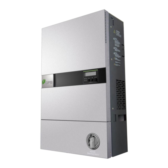
- Page 1 CPS SCA Series Grid-Tied PV-Inverter CPS SCA3/4/5KTL-O/US Installation and Operation Manual Version 1.0...
-
Page 2: Table Of Contents
Table of Contents Before You Start… ....................1 Chapter 1 IMPORTANT Safety Instructions ............2 Chapter 2 Overview .....................5 2.1 Inverter for grid-tied PV systems..............5 2.2 Product features ..................6 2.3 Dimensions of Inverters ................7 2.4 Appearance description ................8 Chapter 3 Installation ..................11 3.1 Inside the Package ................... -
Page 3: Before You Start
This manual contains important information regarding installation and safe operation of this unit. Be sure to read this manual carefully before using. Thank you for choosing this CPS Grid-tied PV Inverter. This PV Inverter is a high performance and highly reliable product specifically designed for the North American Solar market. -
Page 4: Chapter 1 Important Safety Instructions
Chapter 1 IMPORTANT SAFETY INSTRUCTIONS (SAVE THESE INSTRUCTIONS) Please read this user manual carefully before undertaking the installation. CPS reserves the right to refuse warranty claims for equipment damage if the user fails to install the equipment per the instructions in this manual. - Page 5 Warnings and symbols in this document Markings on the product HIGH VOLTAGE: The product works with high voltages. All work on the product must only be performed as described in this document. HOT SURFACE: The equipment is designed to meet international safety standards, but surfaces can become hot during operation.
- Page 6 CAUTION: CPS SCA3/4/5KTL series inverter is approx 38kg (84lbs). Please Check the mounting bracket again before the PV Inverter is hung on to the bracket. At least 2 people are required for this procedure due to the weight of the inverter.
-
Page 7: Chapter 2 Overview
Chapter 2 Overview 2.1 Inverter for grid-tied PV systems CPS SCA3/4/5KTL series inverter is suitable for use with most household grid-tied systems. The system is generally made up of PV-panels, a PV-inverter, an AC-Connection Unit (the connection Interface) and the Grid (Electric Utility) (see Figure 2-1). -
Page 8: Product Features
2.2 Product features Lead-free, RoHS compliant Up to 97.5% peak conversion efficiency Dual MPPT design NEMA 3R outdoor rated enclosure 2x16 LCD display Single phase, 208V L-L or 240V L-L Compact design High reliability with a standard 10 year warranty ... -
Page 9: Dimensions Of Inverters
2.3 Dimensions Figure 2-2 Dimensions of CPS SCA3/4/5K-O/US... -
Page 10: Appearance Description
2.4 Exterior Parts Description Figure 2-3 Exterior Parts Description (1) AC-Output Cable Knockout: ¾” knockout for cable conduit for Grid connection L1 (Line 1), L2 (Line 2)/N (Neutral), GND (PE). (2) Communication Interface Knockout: Use this location for inverter communications wiring. (3) PV-Input Knockouts: Two ¾”... - Page 11 Figure 2-4 Remove the Wiring box terminal cover (5) and (6) AC/DC Wiring Box and Terminals: AC and DC wiring termination. (7) Wiring Box Cover: Transparent plastic cover to protect wiring termination area. (8) Lower Panel: Weather sealed cover for the wiring box...
- Page 12 Figure 2-5 LCD panel (9) Sel/Ent Key: SELECT or ENTER key used to make display menu selections (10) Down Key: Key used to move down the selection list in the display menu (11) Up Key: Key used to move up the selection list in the display menu (12) Alarm Indicator: Red light indicates an alarm that prevents the Inverter from exporting power to Grid.
-
Page 13: Chapter 3 Installation
Chapter 3 Installation Please read the following installation instructions carefully and install the product step-by-step. 3.1 Inside the Package The following items are included in the package: Table 3-1 Main items Item Note Grid-tied PV inverter Mounting bracket Inverter wall mounting bracket Installation and Operation Manual Warranty service card... -
Page 14: Basic Requirements
Snap Bushings/anchors For mounting bracket Safety-lock screws To secure the inverter Mounting plate of the data For optional comm. card logger Ring terminals For wire connections Cable gland For communication ports Seal pin For cable gland holes 3.2 Basic requirements ... -
Page 15: Mounting The Pv-Inverter
3.3 Mounting the PV-Inverter INSTRUCTION: The PV-Inverter can operate at locations where the ambient temperature is up to 60C (140F). However, for optimal power production, it is recommended that inverter is installed where the ambient temperature is between -25C and +45C (-13F ~+113F) To mount the inverter to a wall or structure, please follow these steps: Select a wall or solid vertical surface which is strong enough to support the inverter. - Page 16 Figure 3-1 Inverter mounting dimensions NOTICE: Inverter utilizes natural convection cooling for its heat sink. Mounting the inverter in a horizontal position or having an obstruction on the top of Inverter will result in overheating.
- Page 17 Figure 3-2 Mount the inverter correctly...
- Page 18 Drill the 7 marked holes in the wall using 7/32” bit, and insert concrete anchors (included with Inverter) into the wall. Mount bracket to the anchors using screws (included with Inverter). Figure 3-3 Dimensions of CPS SCA3/4/5KTL bracket holes...
- Page 19 Mount the PV-Inverter onto the base plate as illustrated in Figure 3-4. Figure 3-4 Mount the inverter on the bracket Secure the inverter to the bracket with M6 screw to hold the bottom of inverter to keep the inverter from vibrating against the wall, as shown in Figure 3-5.
-
Page 20: Electrical Installation
3.4 Electrical installation 3.4.1 DC Connection Connections from PV panels to the Inverter are made in the Inverter Wiring Box. Cable type and size should be selected according to the following requirements: Use Class 2 or Class 3 cable, with temperature rating of 194 °F (or 90 °C). ... - Page 21 Figure 3-7 Remove Plastic Protective Cover 5. Configure single MPPT or dual MPPT Single MPPT: This is not a typical configuration. Use a single MPPT if the array design requires it. For example, an array design with 3 input strings that would exceed the Maximum Input Current per MPPT channel may have improved power output if the 3 input strings are combined in a single MPPT.
- Page 22 Figure 3-8 Single MPPT configuration Dual MPPT: i. This is the default configuration from factory and most common use of the product. Connect jumper bar between P48 and P50 on wiring board. Figure 3-9 Dual MPPT configuration 6. Knock out the knockout openings at the bottom of the Wiring Box of Inverter.
- Page 23 Figure 3-10 Knockouts for conduits 7. Install ¾ in. conduit fittings for outdoor use in the knockout openings on the bottom of the Wiring Box of Inverter. Use outdoor fittings to prevent water getting inside Inverter and conduit. All cables from PV string should be routed inside metal conduit.
- Page 24 Figure 3-11 Internal layout of Wiring Box 11. Tighten terminal screws with 15 in-lbs (1.7N-m) of torque. Check that all terminals and cables are secured.
-
Page 25: Ac Connection
3.4.2 AC Connection 1. Switch off circuit breaker in the main switch box to disconnect utility. 2. Put AC/DC disconnect switch to OFF position. 3. Install a ¾ in. conduit fitting for outdoor use in the knockout opening below the Wiring Box of Inverter (refer to Figure 3-12). -
Page 26: Wiring Checklist
7. Tighten terminal screws with 15 in-lbs (1.7N-m) of torque. Check that all terminals and cables are secured. 3.4.3 Wiring Checklist DANGER: High voltages exist between terminals of PV panels when Panel is exposed to sufficient irradiation. Exposed terminals of the PV-Panel can cause electric shock. -
Page 27: Communication Interface
may be required to install between the Inverter(s) and the utility isolation transformer until a pure sine wave is achieved. Any such action must be done by qualified personal and in conjunction with local electrical authorities. Specific guidance is outside the scope of this document. 3.4.4 Communication Interface 3.4.4.1 Standard RS-485 Communication The inverter has integrated RS-485 communications capability. -
Page 28: Optional Ethernet Communication
Figure 3-14 Communication connector on wiring board 3.4.4.2 Optional Ethernet Communication Optional Ethernet Communication board can be installed in the field if such option is purchased by the customer. The optional board assembly can be installed as shown in Figure 3-15. Figure 3-15 Mounting of communication option board assembly... -
Page 29: Chapter 4 Commissioning
Chapter 4 Commissioning 4.1 Start Up The inverter will start up when the following conditions are satisfied: Grid voltage and frequency are within nominal setting. 240V settings: Grid voltage at start-up must be between 216V and 254V 208V settings: Grid voltage at start-up must be between 187V and 220V Grid Frequency must be between 59.5Hz to 60.3Hz PV array voltage is greater than 200V on any one of two MPPT channels. - Page 30 Press three buttons for 5s at the same time in Status Screens will go to the Initial Setup and output switch off. Status Screens ENTER TO SETUP ↓ 1.IEEE1547-240 scroll ENTER TO SETUP ↓ 2.485Adr: 240 ENTER TO SETUP ↓ 3.485Bps: 9600 ENTER TO SETUP ↓...
- Page 31 Choose Inverter RS485 address This is the unique Modbus address of the inverter within a network of inverters and communication devices. The address can be any number between 0 and 99. ENTER TO SETUP ENTER TO ACCEPT ↓ ↕ 2.485Adr: 240 485Adr:240 Figure 4-3 Choose Inverter RS485 address INSTRUCTION:...
- Page 32 ENTER TO SETUP ENTER TO ACCEPT ↓ 4.SET DEFAULT SET DEFAULT Figure 4-5 Clear or default setting Power Factor Setting ENTER TO SETUP ENTER TO ACCEPT ↓ 5.PF SETTING PF:LAG 0.99 ↕ UP/DOWN TO CHANGE NUMBER, ENTER to ACCEPT DEFAULT PF=1.00 Figure 4-6 Adjust PF value PF 1.00: Current is in phase with voltage.
-
Page 33: Start Up Sequence
Exit Configuration When all selections have been properly selected, the installer can go to START INVERTER to enable the inverter to start. Press Enter key to go into the item Press Enter key to exit the Setup Menu, and proceed to start up Inverter ENTER TO SETUP ENTER TO ACCEPT 7.START INVERTE ↓... - Page 34 Check various internal components. Check the disconnecting relays between Inverter and Grid. If any of these tests fails, the inverter will display a fault message about the failure and will not connect to grid. If all Self-Test items pass, the inverter will connect and export power to Grid.
-
Page 35: Chapter 5 User Interface
Chapter 5 User Interface 5.1 Normal Operation and Display Menu 5.1.1 Status Screens After the inverter begins exporting power to the grid, the LCD display automatically scrolls through various information screens, displaying grid and PV array information. The Up and Down keys can be used to go to specific information. - Page 36 Inverter information includes: Display info. Explanation Cummulative energy produced over the entire operating life Etotal of the inverter. This number cannot be reset. Runtime Total run time. This number cannot be reset. Current day energy production. This number is reset to 0 Etoday every time the inverter power is recycled.
-
Page 37: Led Lights
5.1.2 LED Lights There are two LED lights, Green and Red, which indicate the general status of the inverter. Solid ON Inverter is operating correctly and exporting power. Inverter has a minor alarm that does not prevent the Green inverter from exporting power. These alarms could be Flashing (see Section 8 about display messages): ON/OFF... -
Page 38: Inverter Information
Normal Operation ↓ 1.INFORMATION Status Screens scroll Normal Operation ↓ 2.SETTINGS Figure 5-3 Information and settings 5.1.4 Inverter Information In this screen menu, User can review the settings of Inverter. Information includes: Inverter model rating Inverter hardware revision Inverter firmware revision Inverter serial number Inverter Grid voltage and frequency configuration Inverter communication address... -
Page 39: Inverter Settings
Normal Operation INFORMATION ↓ 1.INFORMATION 1.Model 5.0 scroll INFORMATION 2.HW Ver x.001.002 INFORMATION 3.FW Ver x.001.002 UP/DOWN TO CHANGE INFORMATION 4.SN:12345678901 INFORMATION 5.IEEE1547-208 INFORMATION 6.485adr: 1 INFORMATION 7.485Bps: 9600 Figure 5-4 Inverter information 5.1.5 Inverter Settings In this Menu, the user can make changes to the display contrast of the LCD screen and display language. - Page 40 Contrast: There are 5 levels of contrast that user can select to make LCD characters easier to view in different light and temperature conditions. Use Enter key to go into the contrast change screen. Use Up and Down button to make change to contrast of LCD screen. Use Enter key to accept the change.
-
Page 41: Display Messages
5.1.6 Display Messages Monitoring Explanation Parameters Accumulated energy exporting to Grid over the lifetime of Etotal: xxxxx kWhr Inverter in kW-Hr Runtime: xxxxxx Hr Accumulated runtime of Inverter. (5 digit numbers) Etoday: xxxxx WHr Accumulated energy exporting to Grid in that day Power: xxxx W Instantaneous power exporting to grid... - Page 42 GRID FAULT Utility voltage and frequency are outside of operating range PV VOLTAGE HIGH PV array voltage is higher than PV operating range. PV VOLTAGE LOW PV array voltage is lower than PV operating range. OVER TEMP The internal temperature is higher than normal value. EEPROM FAULT EEPROM cannot be written.
-
Page 43: Chapter 6 Preventative Maintenance
Chapter 6 Preventative Maintenance 6.1 Troubleshooting The PV-Inverter requires very little maintenance. When unexpected situation occurs, please refer to the following table for quick troubleshooting before contacting your local service. The following table lists common fault messages and ways to cope with the fault or error. System Fault Explanation Action / Fault Clearance Impedance from PV arrays to Earth Ground... - Page 44 Check DC wiring for signs of arcing or melting, especially at connectors or Sustained arcing in PV wiring is terminals. Replace damaged wires, ARC FAULT detected damaged connectors, or tighten terminals. Need to recycle power to Inverter to restart. Need to recycle power to Inverter. Inverter INTERNAL Failure of self-test on internal will retest relays during Start-up sequence.
-
Page 45: Checking And Maintenance
Inverter could be overheated from exposure to abnormally high ambient temperature or in combination with direct exposure to the internal temperature sun. OVER TEMP higher than normal value Inverter will automatically reconnect to Grid when internal temperature drops operating range. EEPROM EEPROM cannot be written Contact your local service. -
Page 46: Chapter 7 Technical Data
Chapter 7 Technical Data Model Name SCA3KTL-O SCA4KTL-O SCA5KTL-O DC Input Max. PV Power 5.2kW 6.5kW Nominal DC Input Power 3.2kW 4.2kW 5.2kW Max. DC Input Voltage 550Vdc 550Vdc 550Vdc Operating DC Input 150-550Vdc Voltage Range Start-up DC Input 200Vdc Voltage Nominal DC Input 360Vdc... - Page 47 Nominal AC Current @ 13.5A 208Vac Nominal AC Current @ 12.5A 16.7A 20.8A 240Vac Max. AC Current @ 13.5A 208Vac System Max. AC Current @ 13.5A 240Vac System Rated Output Frequency 60Hz Output Frequency Range 59.3-60.5Hz (adjustable) Power Factor >0.99 (±0.95 adjustable) Current THD <3% AC Disconnection Type...
-
Page 48: Chapter 8 Limited Warranty
The warranty policy of this product is specified in the contract; otherwise, the warranty period is 10 years. For service, Chint Power Systems America will provide local support. For Warranty terms, please refer to the CPS America standard warranty policy in place at time of purchase. - Page 49 CHINT POWER SYSTEMS AMERICA CO., LTD. Address: 700 International Parkway, Suite 102 Richardson, Texas 75081 Service Hotline: 855-584-7168 Email: AmericaSales@Chint.com SHANGHAI CHINT POWER SYSTEMS CO., LTD. Headquarters: Building 4, No. 3255, Sixian Road, Songjiang District, Shanghai, China Tele: +86 -21 -3779 1222 -6300 Fax: +86 -21 -3779 1222 -6001 Website: www.chintpower.com/na/ Part No.: 9.0020.0097A0...
Need help?
Do you have a question about the CPS SCA3KTL-O/US and is the answer not in the manual?
Questions and answers