
Related Manuals for Promation Engineering P2 DC Series

Summary of Contents for Promation Engineering P2 DC Series
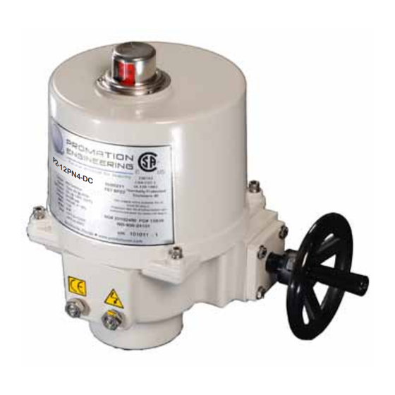
- Page 1 Installation & Operation Manual This IOM is for the following ProMation Engineering Products: P2-12PN4-DC P3-12PN4-DC P2-24PN4-DC P3-24PN4-DC...
- Page 2 This page intentionally left blank...
-
Page 3: Table Of Contents
Field Manual P2/3 DC Series Proportional Control ISO5211 F07 8P22 - D C Table of Contents 2 . . . . . . . . . . . . . . . . . . . Product Specifications 3 . -
Page 4: Product Specifications
Product Specifications Actuator Specifications Torque “lb/Nm 800”lbs/90Nm 1335”lbs/150Nm Supply Voltage 12vdc 24vdc 12vdc 24vdc Max Inrush Current 5.2A 4.5A 4.9A 5.0A Running Current 3.4A 2.2A 4.4A 2.4A Motor DC Brush Type Runtime (90°@60Hz/vdc) 15 sec 22 sec Runtime (90 @50Hz) Duty Cycle Motor Starts 1200 per hour... -
Page 5: Shipping And Handling
Shipping and Handling 1. This actuator is shipped in the FULLY CW position (2 color position indicator REFERENCE DIMPLE shows “CLOSE” and the Reference Dimple aligns with “0”). (The “1” mark is the “0” = CW “1” = CCW FULLY CCW position). 2. -
Page 6: Wiring Diagram
Wiring Diagram Proportional Control Items within dotted line indicates internal components WIRING DIAGRAM FOR DIRECT ACTING AUXILIARY Grn-Open SWITCH (STANDARD) 1 2 3 4 5 AUXILIARY Sig IN+ SWITCH TB-1 Sig IN- (STANDARD) Red - Close Earth ALL SWITCHES -24VDC SHOWN WITH 3 Terminal... - Page 7 Wiring Diagram for P2/3 Series Field Wiring (By Others) External Wiring is the same for units with or without Torque Switches. Torque Switches Identifying Torque Switch Units: Wire sizing data is provided to assist in the selection of the proper wire size for ProMation •...
-
Page 8: Diagram Of Controller
Diagram of Controller Proportional Control LOCATION OF CONTROL CARDS DMC-102 CONTROLLER Dip Switches Red Running CCW (OPEN) Indicator SPAN ZERO Green Running CW (CLOSED) Indicator Motor wire Sensitivity J1T4 J1T3 J1T2 CONTROL INPUT SIGNAL CONFIGURATION XMA-105 FEEDBACK GENERATOR Control Loss of Signal Operation ZERO Type 4-20mA... -
Page 9: Adjusting The Actuator Cw Position
Adjusting the actuator CW position Serious Damage to the actuator will result if the motor is allowed to drive the gear train into the mechanical stop!! Remove power from this device BEFORE making any travel adjustments. This actuator has been factory calibrated to operate between 0 degrees and 90 degrees. Most quarter-turn products will not require recalibration of these settings. -
Page 10: Adjusting The Actuator Ccw Position
Adjusting the actuator CCW position Serious Damage to the actuator will result if the motor is allowed to drive the gear train into the mechanical stop!! Remove power from this device BEFORE making any travel adjustments. This actuator has been factory calibrated to operate between 0 degrees and 90 degrees. Most quarter-turn products will not require recalibration of these settings. -
Page 11: Adjusting The Actuator Auxiliary Switches
Adjusting the actuator Auxiliary Switches Adjust Cam 3 1. The THIRD cam is Cam 3, the CW auxiliary switch adjustment. Drive the actuator to its CW position. Then use a 2.5mm hex key to free up the cam set screw. Once it is free, rotate the hex key to the RIGHT 10- 15 degrees to reset the switch roller arm. - Page 12 4/25/2013 Checked By Last Checked: Dwg. Name 4/8/2015 P2_3 F07 8P22 DimData.idw This Document is the property of ProMation Engineering, Page 10 of 14 P2/3 12VDC Proportional Series Inc. Distribution of this document without the written Material Finish Rev. consent of the owner is Strictly forbidden.
-
Page 13: Mechanical Data
Mechanical Data P Series Exploded View (P2/3-120N4 unit is shown) Easily distinguishable yellow/red position Aluminum Casting indicator NEMA 4X Protection Heavy Duty Drive Motor Modular Easily accessible Control switch & cam stacks Cards Aluminum Casting NEMA 4X Protection NEMA 4X Cover Seal Worm Drive Switch Logic Map and... -
Page 14: Calibrating The Proportional Control Board
Calibrating the proportional control board This procedure will assume that the actuator is installed correctly both mechanically and electrically with correct POWER and SIGNAL. 1. Actuator is in full CLOSED position. Preset the Feedback and Trip Adjust 2. Disconnect the motor wire from terminal J1T4 (DMC-102). DMC-102 CONTROLLER 3. -
Page 15: Commissioning
Commissioning After completing all mounting and wiring procedures and main power is available, it is now possible to commission the actuator. 1. Utilize the handwheel to rotate the actuator and damper, valve or other connected device through its full travel from fully CW to fully CCW and back again to check for any possible interference. - Page 16 ProMation Engineering, Inc . 16138 Flight Path Drive Brooksville, FL 34604 Phone (352) 544-8436 Fax (352) 544-8439 www .promationei .com...
- Page 17 ProMation Engineering can provide design and technical services for OEM’s, projects with customized requirements and specialized operations. ProMation Engineering follows a policy of continual product updates and enhancements. Our website is the best place to obtain the latest product documentation, including the wiring diagrams for these controllers.