Table of Contents
Advertisement
Quick Links
Advertisement
Table of Contents

Related Manuals for Kuppersbusch IKEF 248-5


Summary of Contents for Kuppersbusch IKEF 248-5
- Page 1 Refrigerators IKEF 248-5 IKEF 238-5...
- Page 2 Service Manual: H8-420-02-06 Responsible: Uwe Laarmann KÜPPERSBUSCH HAUSGERÄTE AG E-mail: uwe.laarmann@kueppersbusch.de Tel.: (0209) 401-732 Kundendienst Fax: (0209) 401-743 Postfach 100 132 Date: 01.04.2005 45801 Gelsenkirchen...
-
Page 3: Table Of Contents
Function chart....................... 12 How the refrigerators operate ..................13 IKEF 238-5 ......................13 IKEF 248-5 ......................16 Acoustic alarm (both models) ................17 Accessing the components in the keep-fresh cooling zone ........18 Battery-driven evaporator and evaporator sensor ..........18 0°... -
Page 4: Safety Instructions
Service Manual Safety instructions Danger! Repairs may only be carried out by a qualified electrician! Inexpert repairs may lead to risks and damages for the user! To prevent electric shocks, please observe the following tips: • In the event of faults, housing and frame may be live! Prior to repairs, disconnect the appliance from the mains! •... -
Page 5: Introduction
The IKEF 238-5 is a refrigerator with a standard refrigerator compartment and a 4-star freezer compartment. The PNC is type 923457xxx (195 4S). The IKEF 248-5 is a refrigerator with a standard refrigeration compartment and a 0° keep-fresh cooling zone. The PNC is type 923524xxx (210 CC). -
Page 6: Measuring The Temperature
Service Manual Measuring the temperature The temperature is measured with 3 or 4 sensors: • Refrigerator sensor (at the fan) • 0° sensor (on the casing of the keep-fresh cooling zone) • Sensor of the battery-driven evaporator (on the battery itself) •... -
Page 7: Air Flow
Service Manual Air flow The cold generated by the battery-driven evaporator (located in the keep-fresh cooling zone behind the evaporator cover E) is firstly spread by the fan located behind the fan casing C into the keep-fresh cooling zone and then into the standard refrigeration compartment. The air is sucked in by the fan which is located in the top part of the refrigeration compartment. -
Page 8: Appliance Components
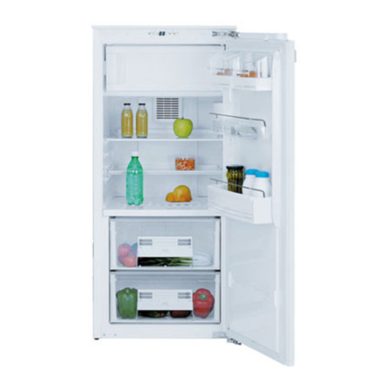
Service Manual Appliance components Front view The most important appliance components are: Control panel Butter compartment Door compartment Bottle shelf Keep-fresh cooling zone drawer (see note a) Divider plate Shelves Air filter (special fitting, see note b) Freezer compartment door 10. -
Page 9: Rear View
Service Manual Rear view The most important appliance components are: Drainage filter Operating condensor Compressor Additional drip cup for water (IKEF 248-5 only) Drip cup for water For internal use only... -
Page 10: Cooling Circuit
Cooling circuit IKEF 238-5 Compressor Evaporator Frame heater Dryer Capillary tube Tube evaporator Battery-driven evaporator (keep-fresh cooling zone) Heat exchanger IKEF 248-5 Compressor Condensor Frame heater Dryer Capillary tube Battery-driven evaporator (keep-fresh cooling zone) Heat exchanger For internal use only... -
Page 11: Electric System
Service Manual Electric system Please observe the circuit diagrams for the respective models. Compressor Protective motor switch 13 Lamp 28 Operating condensor 41 ERF 2000 electronic unit yellow-green brown blue white black For internal use only... -
Page 12: Function Chart
Service Manual Function chart Please observe the circuit diagrams for the respective models. Compressor Protective motor switch 13 Lamp 28 Operating condensor 41 ERF 2000 electronic unit yellow-green brown blue white black Cable Neutral wire For internal use only... -
Page 13: How The Refrigerators Operate
Service Manual How the refrigerators operate IKEF 238-5 7.1.1 Refrigerator compartment control panel 6 = Display for activated superfrost 1 = Performance display (green) function (yellow) for rapid freezing in the freezer compartment 2 = Cooling/OFF button 7 = Superfrost button 3 = Button for setting the temperature (for higher 8 = Display for activated rapid-cool temperatures) - Page 14 Service Manual 7.1.4 Temperature display The temperature display (4) indicates several functions: • For standard operation the ACTUAL temperature will be shown. • While the temperature is being adjusted, the refrigerator temperature which has currently been set will blink (pre-set temperature). Attention! It is quite normal for the temperature display to indicate the actual temperature with a slight delay.
- Page 15 Service Manual 7.1.9 Defrosting the battery-driven evaporator The ice which builds up on the battery-driven evaporator needs to be defrosted at regular intervals. The battery-driven evaporator is defrosted every 4 hours of compressor operation. The defrost phase commences when the compressor is switched off. During the defrost phase: •...
-
Page 16: Ikef 248-5
Service Manual IKEF 248-5 The operation of the refrigerator varies depending on the refrigeration requirement of the keep-fresh cooling zone and the standard refrigeration compartment. There are three possible combinations for standard operation: • Need for refrigeration in the keep-fresh cooling zone only •... -
Page 17: Acoustic Alarm (Both Models)
Service Manual 7.2.4 Defrosting the battery-driven evaporator The ice which builds up on the battery-driven evaporator needs to be defrosted at regular intervals. The battery-driven evaporator is defrosted every 4 hours of compressor operation. The defrost phase commences when the compressor is switched off. During the defrost phase: •... -
Page 18: Accessing The Components In The Keep-Fresh Cooling Zone
Service Manual Accessing the components in the keep-fresh cooling zone Battery-driven evaporator and evaporator sensor Proceed as follows in order to access the battery-driven evaporator and the temperature sensor: Remove the top cover of the 0° drawer. Remove the 0° drawer. Remove the divider plate. -
Page 19: 0° Sensor
Service Manual 0° sensor Proceed as follows in order to access the 0° sensor: Remove the top cover of the 0° drawer. Remove the 0° drawer. Use a screwdriver with a flat edge and 0° sensor remove the protective grating of the 0°... -
Page 20: Accessing The Components In The Refrigerator
Service Manual Accessing the components in the refrigerator Fan and refrigerator sensor First remove the cover of the evaporator. Then proceed as follows: Remove the top cover of the 0° drawer. Remove the 0° drawer. Remove the divider plate. Remove the two fastening screws of the 5. - Page 21 Service Manual Now remove the fan casing as follows: Loosen the two fastening screws of the A Fan terminal fan casing and pull the casing out B Refrigerator sensor downwards. Now the fan and the refrigerator sensor can be removed as follows: Remove the refrigerator sensor from the 2.
-
Page 22: Control Panel
Service Manual Control panel In order to gain access to the control panel and its components (power electronics unit, display electronics unit, electronic unit of the fan and the terminals), proceed as follows: Remove the two screw covers and remove the Remove the protective sheet. - Page 23 2. unoccupied 3. Cable 4. Compressor 5. Neutral wire 6. Neutral wire 7. Lamp 8. Unoccupied (IKEF 248-5) Neutral wire (IKEF 238-5) 9. Unoccupied (IKEF 248-5) Compensating heating elements (IKEF 238-5) 1. Electronic unit for the fan 2. Neutral wire 1.
- Page 24 Service Manual 1. Unoccupied 2. Unoccupied 1. Unoccupied 2. Unoccupied 3. Unoccupied 4. Unoccupied 1. Unoccupied 2. Unoccupied 9.2.2 Electronic unit for the fan 1. Cable (power supply electronic unit); 2. Neutral wire (power supply electronic unit); 4. + Vcc (fan power supply); 5.
- Page 25 Service Manual 9.2.3 Display electronic unit IKEF 238-5 IKEF 248-5 ON/OFF button ON/OFF button Button to raise the temperature Button to raise the temperature Button to reduce the temperature Button to reduce the temperature FROSTMATIC button COOLMATIC button COOLMATIC button...
-
Page 26: Design For Models With An Air Filter
Service Manual Design for models with an air filter Depending on the model, the middle channel will be replaced by a filter channel. Middle channel Filter channel Open the flap and replace the charcoal filter at least once a year. It is recommended that a charcoal filter be used for models with an air filter. -
Page 27: Technical Features
Power electronic unit: Software version......NFBF4A0N Electronic unit version ....ERF2000P-01.A Display electronic unit: EEPROM........F00F2 Electronic unit version ....ERF2000D-06.A 11.2 IKEF 248-5 Compensating heating element: Voltage (V) ........240 Power [W]........4 Resistance [ohm]......14400 Fan: Type: ..........3414 NMR-418 Voltage [V DC]......18 . . 26 Power [W]........1.8...
Need help?
Do you have a question about the IKEF 248-5 and is the answer not in the manual?
Questions and answers