Table of Contents
Advertisement
Quick Links
Advertisement
Table of Contents

Subscribe to Our Youtube Channel
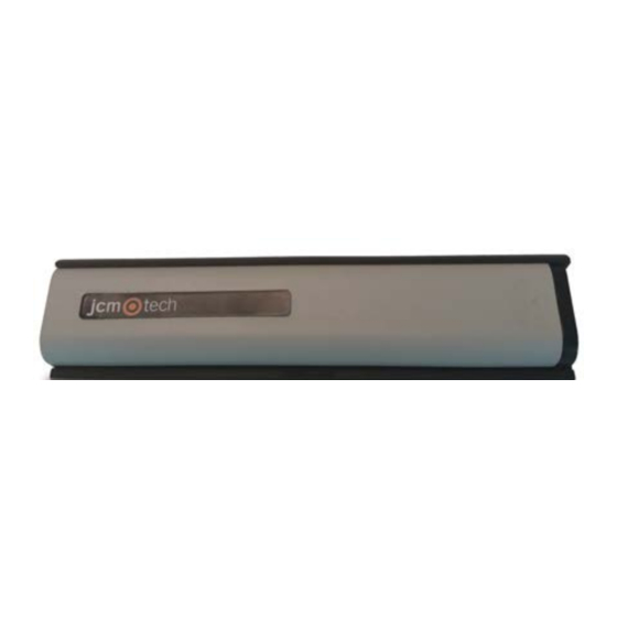
Summary of Contents for jcm-tech RB3 TGL868
- Page 1 RB3 TGL868 User Manual...
-
Page 2: Table Of Contents
Table of contents Important safety instructions Use of the equipment Introduction Installation Connection Programming Starting up IN1 and IN2 connections Programming transmitter to receiver Programming of one safety transmitter (IN1 input) Programming of two safety transmitters (IN1 and IN2 input) Check the correct operation Maintenance Leds and beeps indication table... -
Page 3: Important Safety Instructions
Important safety instructions Disconnect the power supply whenever you proceed to the installation or repair of the equipment. In compliance with the European Low Voltage Directive, we inform you of the fol- lowing requirements: •When the devices remain permanently connected, an easily accessible connecting device must be incorporated into the wiring. -
Page 4: Introduction
Introduction The RadioBand system is designed of domestic, commercial and industrial door applications where a safety edge is used. The system provides a wireless system replacing spiral cables or energy chain systems to provide the safety signal to the door or gate control panel. The receiver monitors the status of transmitters connected to it. -
Page 5: Installation
Installation Connection IN1 Connection SW1:1 SW1:2 JCM Optical safety edge (OSE-S7502B and OSE- S7502) Standard optical safety edge 8k2 resistive safety edge NC contact* IN2 Connection SW1:3 NC contact* 8k2 resistive safety edge * In order to comply with the EN 12453:2017 safety standard, NC contact input can not be used to connect safety devices. - Page 6 8k2 RESISTIVE SAFETY EDGE / MECHANICAL OR CONTACT DEVICES OSE-S7502 “ALWAYS ON” OPTICAL SAFETY EDGE jcmtechnologies...
- Page 7 STANDARD OPTICAL SAFETY EDGE (Only used with ATEST function) OSE-S7502B “ALWAYS ON” OPTICAL SAFETY EDGE OSE-S7502B “ALWAYS ON” OPTICAL SAFETY EDGE AND WICKET DOOR CONTACT jcmtechnologies...
-
Page 8: Programming
Programming Starting up IN1 and IN2 connections See Table IN1 CONNECTION. * These two configurations are supported only if work- ing in WORK mode in the receiver. In programming mode, the receiver will warn us that it cannot support these con- figurations, emitting 6 continuous beeps and leaving programming mode. -
Page 9: Programming Of One Safety Transmitter (In1 Input)
Programming of one safety transmitter (IN1 input) Configuration of transmitter programming Mode in the receiver. Led R1 Led R2 Safety edge activates relay 1 on the receiver Safety edge activates relay 2 on the receiver Safety edge activates the two relays 1 and 2 at the same time Programming of two safety transmitters (IN1 and IN2 input) Safety edge in IN1 activates relay 1 and... -
Page 10: Maintenance
Maintenance Leds and beeps indication table The status of leds is shown during 5 minutes after pressing PROG button or during the Check function. The rest of the time they are turned off. IN1/IN2 Beeps Equipment Message Solution Safety edge activ- beeps transmitter ated... -
Page 11: Batteries
Batteries Storage •Store the lithium cells in a cool, dry and ventilated area far from fires and heating sources. •It is recommended the use of a non-combustible structure and keep adequate clear- ance between walls and batteries. •The maximum temperature suggested for the storage is +30°C. •Higher temperatures are allowed but cause an increase in the self discharge of the battery and speed up the process of passivation. -
Page 12: Technical Data
Regulatory Data EU Declaration of conformity JCM TECHNOLOGIES, S.A. hereby declares that the product RB3 TGL868 complies with the relevant fundamental requirements of the RED Directive 2014/53/EU, as well as with the Machine Directive 2006/42/EC whenever its usage is foreseen; and with the 2011/65/EU RoHS Directive.


Need help?
Do you have a question about the RB3 TGL868 and is the answer not in the manual?
Questions and answers