Table of Contents
Advertisement
Quick Links
Advertisement
Table of Contents

Related Manuals for jcm-tech RADIOBAND3G


Summary of Contents for jcm-tech RADIOBAND3G
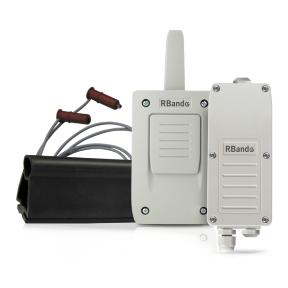
- Page 1 RB3 R868, RB3 T868, RB3 T868W & RB3 R868W User Manual...
-
Page 2: Table Of Contents
Table of contents Important safety instructions Use of the equipment Introduction Operating Receiver RB3 R868 Transmitter RB3 T868 Assembly and installation Installation of the equipment Connecting the receiver to the control panel Adjustment of the receiver / Operating modes ON/WORK mode ATEST signal Connecting the safety edge to the transmitter Programming... -
Page 3: Important Safety Instructions
EU Declaration of conformity Important safety instructions Disconnect the power supply whenever you proceed to the installation or repair of the equipment. In compliance with the European Low Voltage Directive, we inform you of the fol- lowing requirements: •When the devices remain permanently connected, an easily accessible connecting device must be incorporated into the wiring. -
Page 4: Introduction
Introduction Operating The RadioBand system is designed for Domestic, Commercial and Industrial door and gate applications where a safety edge is used. The system provides a wireless system replacing spiral cables or energy chain sys- tems to provide the safety signal to the door or gate control panel. The receiver continuously monitors the status of transmitters connected to it. -
Page 5: Receiver Rb3 R868
Receiver RB3 R868 jcmtechnologies... -
Page 6: Transmitter Rb3 T868
Transmitter RB3 T868 jcmtechnologies... -
Page 7: Assembly And Installation
Assembly and installation Installation of the equipment jcmtechnologies... - Page 8 jcmtechnologies...
-
Page 9: Connecting The Receiver To The Control Panel
Connecting the receiver to the control panel Connecting the safety outputs to control panel. Example: connection to control panel with safety contact / STOP input Example: connection to control panel with input for safety edge 8k2 The equipment can be connected to the control panel with input for safety edge 8k2 or directly into a safety input normally closed contact as if it were a photocell or stop signal. -
Page 10: Adjustment Of The Receiver / Operating Modes
Adjustment of the receiver / Operating modes ↑ Any change in the configuration of the switches needs a reprogramming of the system (see "Programming"). ↓ Interference detector ↑ 7 s The equipment is switched to safety state after 7s. ↓ The equipment is switched to safety state after 265ms. -
Page 11: On/Work Mode
ATEST signal polarity (depends on the control panel) ATEST negative: ATEST signal is a fixed 12 or 24V signal ↑ Negative that the control panel sets to 0V to make the system check. ATEST positive: ATEST signal is disconnected and when ↓... -
Page 12: Atest Signal
ATEST signal In order to comply with EN ISO 13849-1: 2015 safety standard, a signal to test the system before each door cycle must be connected to the control panel. When working with optical safety edges, in ON mode, only OSE-S7502B and OSE- S7502 are allowed as they are kept always active. -
Page 13: Connecting The Safety Edge To The Transmitter
Connecting the safety edge to the transmitter Connection examples IMPORTANT: The position of the selector must correspond to the type of safety edge connected. IN 2 only supports 8k2 resistive safety devices and mechanical / contact devices. The selector 3 is not applicable if nothing is con- nected to IN2. - Page 14 jcmtechnologies...
-
Page 15: Programming
Programming •Working with one safety edge, it must be connected to IN1 of the transmitter. IN2 does not work. This band can work on R1 (mode 1) or R2 (mode 2) or sim- ultaneously on the 2 relays (mode 3). •Working with two safety edges (mode 4), the safety edge connected to IN1 act on R1 and the safety edge IN2 connected on R2. -
Page 16: Mode 1: Safety Edge Connected To In1 Activates R1
Mode 1: Safety edge connected to IN1 activates R1 Safety edge connected in IN1 will activate R1. Employed receiver memory = 1 transmitter Programming sequence: •Press PROG button on the receiver (1) until R1 LED lights (2). •Press PROG button on the transmitter (3). •A beep will be heard on the receiver indicating the transmitter is properly pro- grammed (4). -
Page 17: Mode 2: Safety Edge Connected To In1 Activates R2
Mode 2: Safety edge connected to IN1 activates R2 Safety edge connected in IN1 will activate R2. Employed receiver memory = 1 transmitter Programming sequence: •Press PROG button on the receiver (1) until R2 LED lights (2). •Press PROG button on the transmitter (3). •A beep will be heard on the receiver indicating the transmitter is properly pro- grammed (4). -
Page 18: Mode 3: Safety Edge Connected To In1 Activates R1 And R2
Mode 3: Safety edge connected to IN1 activates R1 and R2 Safety edge connected in IN1 will activate R1 and R2. Employed receiver memory = 2 transmitters Programming sequence: •Press PROG button on the receiver (1) until R1 LED and R2 LED light (2). •Press PROG button on the transmitter (3). -
Page 19: Mode 4: Safety Edge Connected To In1 Activates R1 And Safety Edge Connected To In2 Activates R2
Mode 4: Safety edge connected to IN1 activates R1 and safety edge connected to IN2 activates R2 Safety edge connected in IN1 will activate R1 and IN2 will activate R2. Employed receiver memory = 2 transmitters Programming sequence: •Press PROG button on the receiver (1) until R1 LED and R2 LED flash (2). •Press PROG button on the transmitter (3). -
Page 20: Checking And Maintenance
Checking and maintenance Does the equipment work properly? Once the safety edge is wired and programmed into the receiver, R1 and / or R2 (according to programming mode) is at standby state (off), also IN1 and IN2 at the transmitter. If the safety edge has been programmed in R1 and R1 LED is at ON, check that the safety edge is not pushed/detecting (IN1 LED at ON on the transmitter) or it is not properly configured (IN1 LED flashing on the transmitter). -
Page 21: Check Function
CHECK function Ideal to know the radio coverage of the installation. Press the receiver’s CHECK button for at least 1 second to enter check mode. The indicator light will come on and four beeps will be heard. Perform a complete door opening and closing manoeuvre. During the system check a beep will be heard every 1,5 seconds. -
Page 22: Troubleshooting
Troubleshooting jcmtechnologies... -
Page 23: Batteries
Batteries Storage •Store the lithium cells in a cool, dry and ventilated area far from fires and heating sources. •It is recommended the use of a non-combustible structure and keep adequate clearance between walls and batteries. •The maximum temperature suggested for the storage is +30°C. •Higher temperatures are allowed but cause an increase in the self discharge of the battery and speed up the process of passivation. -
Page 24: Technical Data
Technical data Glands must be installed to ensure IP65. Replace glands for caps on the cable entries that are not used. Battery life time: 2 years approximately. With standard low power opto safety edges, the life time will depend on the working mode and the number of maneuvres per day. - Page 25 RB3 R868 RB3 T868 Multifrequency system 868 MHz auto-adjustable (Channel 1: 868,700 -869,200MHz¸Channel 2: Frequency 868,000 -868,600MHz; Channel 3: 869,400 - 869,650MHz; Channel 4: 869,400 -869,650MHz) 6 transmitters (3 on relay Memory 1, 3 on relay 2) Operating con- Max 255mA 12mA sumption Radiated power...
-
Page 26: Notes
Notes jcmtechnologies... - Page 27 Notes jcmtechnologies...
-
Page 28: Regulatory Data Uk Declaration Of Conformity
RED Directive 2014/53/EU, as well as with the Machine Directive 2006/42/EC whenever its usage is foreseen; and with the 2011/65/EU RoHS Dir- ective. See website https://www.jcm-tech.com/declarations/ JCM TECHNOLOGIES, S.A. C/COSTA D'EN PARATGE, 6B 08500 VIC (BARCELONA) SPAIN...
Need help?
Do you have a question about the RADIOBAND3G and is the answer not in the manual?
Questions and answers