Advertisement
Quick Links
Advertisement

Related Manuals for GLITZHOME 5022000


Summary of Contents for GLITZHOME 5022000
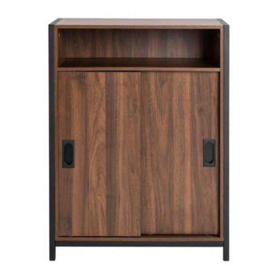
- Page 1 Assembly Instruction TWO DOOR WOOD CABINET...
- Page 2 PRE-ASSEMBLY PREPARATION WARNING: MAXIMUM LOAD NOT EXCEED 10LBS ON SHELVES. • CAUTION: Assembly will require at least 2 adults. DO NOT use power tools.To prevent serious injury or death, this product is equipped with a wall anchoring system. Before this product can be used, the wall anchoring system must be installed as directed in the assembly instructions.
- Page 3 PART DESCRIPTION PART DESCRIPTION LEFT FRAME LEFT DOOR RIGHT FRAME BOTTOM PANEL FRONT BOTTOM SUPPORT BAR TOP PANEL BACK BOTTOM SUPPORT BAR BACK PANEL BACK CROSS BAR TOP FIXED SHELF PANEL LEFT SIDE PANEL MIDDLE MOBILE SHELF PANEL RIGHT SIDE PANEL BACK PLASTIC STRIP RIGHT DOOR PARTS LIST...
- Page 4 TOP FIXED SHELF MIDDLE MOBILE PANEL BACK PLASTIC STRIP PANEL (M) Qty: 1 Qty: 1 Qty: 2 HARDWARE LIST CAM (1) CAM LOCK (2) PHILLIPS SCREW (3) UMBRELLA HEAD BOLT Ø15*9mm Ø4*37mm M6*25mm Qty: 8 Qty: 8 Qty: 4 Qty: 6 PHILLIPS SCREW (5) ALLEN BOLT (6) PIN (7)
- Page 5 REQUIRED HARDWARE IN THIS STEP DESCRIPTION SKETCH 2PCS GLUE STEP 1 Insert cam (1) into left wood panel (F) and fully tighten. Place a small dab of glue into the adjacent holes as shown in the diagram. REQUIRED HARDWARE IN THIS STEP SKETCH DESCRIPTION 2PCS...
- Page 6 REQUIRED HARDWARE IN THIS STEP DESCRIPTION SKETCH WOOD DOWEL 4PCS GLUE STEP 3 Place a small dab of glue (11) into the outside holes on the edge of top fixed shelf panel (M) and insert wood dowels (10) into the holes. STEP 4 Place top fixed shelf panel (M) on edge.
- Page 7 REQUIRED HARDWARE IN THIS STEP DESCRIPTION SKETCH 4PCS CAM LOCK PHILLIPS SCREW DRIVER NOT INCLUDED STEP 5 Insert cam lock (2) into top fixed shelf panel (M) and tighten with phillips screw driver. REQUIRED HARDWARE IN THIS STEP DESCRIPTION SKETCH 4PCS GLUE STEP 6...
- Page 8 REQUIRED HARDWARE IN THIS STEP DESCRIPTION SKETCH WOOD DOWEL 4PCS GLUE STEP 7 Carefully set the assembled panels upright as shown in the diagram. Place a small dab of glue (11) into the outside holes of the edges of left wood panel (F) and right wood panel (G) and insert wood dowels (10) into the holes.
- Page 9 REQUIRED HARDWARE IN THIS STEP DESCRIPTION SKETCH 4PCS CAM LOCK PHILLIPS SCREW DRIVER NOT INCLUDED STEP 9 Insert cam lock (2) into left wood panel (F) and right wood panel (G) and fully tighten with phillips screwdriver. REQUIRED HARDWARE IN THIS STEP DESCRIPTION SKETCH WOOD DOWEL...
- Page 10 STEP 11 Slide back panel (L) into the grooves of left wood panel (F) and right wood panel (G). Place plastic strip (O) in between each back panel (L) as shown in the diagram.
- Page 11 REQUIRED HARDWARE IN THIS STEP DESCRIPTION SKETCH GLUE STEP 12 Place a small dab of glue (11) into the outermost holes bottom wood panel (J) as shown in the diagram. STEP 13 Align the wood dowels of left wood panel (F) and right wood panel (G) with the holes in bottom wood panel (J) and lower into place.
- Page 12 REQUIRED HARDWARE IN THIS STEP DESCRIPTION SKETCH PHILLIPS SCREW Ø4*37mm 4PCS PHILLIPS SCREW DRIVER NOT INCLUDED STEP 14 Secure the bottom wood panel (J) to left wood panel (F) and right wood panel (G) with phillips screw (3) using phillips screwdriver. Fully tighten screws. REQUIRED HARDWARE IN THIS STEP DESCRIPTION SKETCH...
- Page 13 STEP 16 Carefully place the assembled metal frame over the assembled cabinet as shown in the diagram.
- Page 14 REQUIRED HARDWARE IN THIS STEP DESCRIPTION SKETCH ALLEN BOLT M6*25MM 4PCS PHILLIPS SCREW Ø4*29MM 6PCS ALLEN WRENCH PHILLIPS SCREW DRIVER NOT INCLUDED STEP 17 Attach the the metal frame to bottom wood panel (J) with phillips screw (5) using phillips screwdriver.
- Page 15 REQUIRED HARDWARE IN THIS STEP DESCRIPTION SKETCH PHILLIPS SCREW Ø4*12MM 4PCS PHILLIPS SCREW DRIVER NOT INCLUDED STEP 18 With assistance, carefully turn the assembled cabinet onto it's feet as shown in the diagram. Attach back cross bars (E) with phillips screw (8) using phillips screwdriver.
- Page 16 REQUIRED HARDWARE IN THIS STEP DESCRIPTION SKETCH 4PCS STEP 20 Insert pin (7) into the pre-drilled holes of left wood panel (F) and right wood panel (G) as shown in the diagram. Then p the middle mobile shelf panel (N) onto the pins (7). The shelf can be lace adjusted up or down by moving the level of the pins (7).
- Page 17 STEP 22 Place the wheels of left door (I) in the back bottom chute. Align the top of the left door with the back upper slot and press the buttons on the back of the door to release the pins. Press this pin and the guide rod will slide into the slot First put the wheels into...
- Page 18 STEP 24 Place the wheels of right door (H) into the bottom front chute. Align the top of the door with the top front slot and press the buttons on the back of the door to release the pins. Press this pin and the guide rod will slide into the slot guide rod will slide into the slot...
- Page 19 REQUIRED HARDWARE IN THIS STEP DESCRIPTION SKETCH 1 PC PHILLIPS SCREW Ø4*12mm 1 PC ANTI-TIPPING STRIP 1 PC WALL ANCHOR Ø 8.5*30mm 1 PC PHILLIPS SCREW Ø 4*25mm 2 PCS STEEL PLATE NOT INCLUDED PHILLIPS SCREW DRIVER NOT INCLUDED NOT INCLUDED WALL WALL NOT INCLUDED...
- Page 20 STEP 27 To avoid injury, please open the cabinet doors as directed in the diagram.
Need help?
Do you have a question about the 5022000 and is the answer not in the manual?
Questions and answers