Table of Contents
Advertisement
Available languages
Available languages
Quick Links
Advertisement
Table of Contents

Subscribe to Our Youtube Channel
Related Manuals for MGF HELPADENT


Summary of Contents for MGF HELPADENT
- Page 1 HELPADENT USE AND MAINTENANCE INSTRUCTION HANDBOOK Version, march 2003) MGF S.r.l. V. Volta 79 20090 CUSAGO (Milano) – Italy tel. + 39.02.90.19.180 fax +39.02.90.19.273 info@mgfcompressors.it www.mgfcompressors.it...
-
Page 2: Table Of Contents
CONFORMITA’ ALLE DIRETTIVE CEE ....................... 3 CONTROLLO GENERALE ............................3 GARANZIA ................................3 DOVE INSTALLARE L’UNITA’ HELPADENT..................... 3 DESCRIZIONE FUNZIONAMENTO COMPRESSORE UNITA’ HELPADENT ..........4 MANUTENZIONE DEL COMPRESSORE ......................5 DIMENSIONI E CARATTERISTICHE TECNICHE ....................5 Capacità serbatoio............................... 5 Aria aspirata................................5 Pressione massima di funzionamento ......................... -
Page 3: Conformita' Alle Direttive Cee
La MGF S.r.l. garantisce il buon funzionamento dell’unità HELPADENT per la durata di mesi dodici (12) a far data del documento di trasporto. Entro i termini suddetti MGF si impegna a sostituire e riparare gratuitamente le parti che, a giudizio insindacabile del servizio tecnico, presentano vizi di fabbricazione o di materiale. -
Page 4: Descrizione Funzionamento Compressore Unita' Helpadent
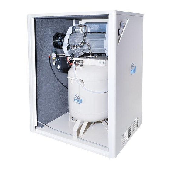
7) Serbatoio aria da 4 Lt 8) Rubinetto di scarico condensa 9) Manometro d.40 1/8” 10) Filtro regolatore 11) Pressostato 12) Valvola di sicurezza 13) Tubo flessibile di mandata aria 14) Valvola di non ritorno DESCRIZIONE FUNZIONAMENTO COMPRESSORE UNITA’ HELPADENT... -
Page 5: Manutenzione Del Compressore
Prima di tutto assicurarsi che l’unità HELPADENT sia posizionata su un pavimento in piano per evitare che essa abbia dei movimenti anomali. Verificare che il voltaggio corrisponda a quello stampato sull’etichetta identificativa al lato del compressore. Assicurarsi che l’interruttore montato sul pressostato sia posizionato su off, quindi collegare l’apparecchio alla rete elettrica ed avviare il compressore. -
Page 6: Schema Di Flusso Unita' Helpadent
ATTENZIONE Al fine di individuare eventuali danneggiamenti sulle bottiglie è opportuno controllare il loro stato prima di utilizzare l’unità HELPADENT; se queste dovessero apparire tali si deve provvedere alla loro immediata sostituzione. Le bottiglie non devono mai essere lavate in lavastoviglie e la pressione al loro interno non deve... -
Page 7: Regolatore A Pedale
Gli ablatori aria-acqua e solo acqua sono equipaggiati con una connessione di tipo MID WEST REGOLATORE A PEDALE In dotazione all’unità HELPADENT vi è un comando di pressione a pedale il quale permette di regolare la pressione di lavoro sugli ablatori agendo con il piede sul disco regolatore. -
Page 8: Manutenzione Sistema Ablatori
L’utilizzo di alcuni prodotti per la pulizia e la disinfezione potrebbe creare danni o compromettere il corretto funzionamento degli strumenti dentali (siringa ed ablatori). La garanzia MGF non copre eventuali danni che possano scaturire da un utilizzo errato di questi prodotti. - Page 9 LISTA RICAMBI Pos. Descrizione Codice Coperchio alettato in alluminio 7301 Tappo olio - filtro aspirazione 4251 Motocompressore da 0,5 Hp 7302 Morsettiera completa 7540 Condensatore 7528 Spia livello olio da 1/2" 8017 Assieme châssis - serbatoio aria da 4Lt 7632 Rubinetto scarico condensa 5079 Manometro d.
-
Page 10: English Version
Warranty certificate WARRANTY The correct performance of the HELPADENT unit is guaranteed by MGF S.r.l. for a period of 12 (Twelve) months starting from the delivery notes. During this period MGF commits itself to replace or repair any parts that on MGF service department opinion should be damaged by faulty material or bad workmanship free of charge. - Page 11 COMPRESSOR COMPOSITION Components description: 15) Aluminium cap 16) Oil plug / Aspiration filter 17) 0,5 Hp motor- compressor 18) Electric terminal board 19) Condenser 20) ½” Oil level window 21) 4 Lt air receiver 22) Water relief 23) D.40 1/8” pressure gauge 24) Pressure reducer filter 25) Pressure switch 26) Safety valve...
-
Page 12: Helpadent Unit Compressor Working Description
HELPADENT UNIT COMPRESSOR WORKING DESCRIPTION Firstly ensure the HELPADENT unit is on level ground. Do not allow it to run if it is standing on an incline. Check also that mains voltage corresponds with that shown on the data label on the side of the compressors. -
Page 13: Helpadent Unit System Diagram
HELPADENT UNIT SYSTEM DIAGRAM WATER TO SYRINGE AND HANDPIECE PRESSURE HEAD 3 WAYON/OFF WATER REGULATED AIR 2,2 BAR - 30 psi BOTTLE PICK UP TUBE INCOMNG AIR 6 BAR - 80 psi The air delivered by compressor at 6 BAR – 80 psi get in to the system small regulator to get out it at about 2,2 BAR –... -
Page 14: Helpadent Units Control Functions
HELPADENT UNITS CONTROL FUNCTIONS All controls on the MT520 Wall Mount Manual Handpiece Control are located on the side and front panels. Figure A shows the location and identifies the function of these controls. 1-Drive air pressure gauge Indicates drive air pressure to the handpiece 2-Handpiece selector Used to select handpiece 1 or handpiece 2. -
Page 15: Water Line Maintenance
WATER LINE MAINTENANCE Daily The most convenient way to maintain water lines in your HELPADENT unit is to use an empty and dry bottle after you disconnect the unit from the power in and let the unit unpressured. Connect the unit to the power input and wait for the unit reaching the working pressure (6 BAR- 80 psi). - Page 16 SPARE PARTS LIST Pos. Description Code Aluminium cap 7301 Oil plug – Aspiration filter 4251 0,5 Hp Pump-motor 7302 Electric connection terminal 7540 Condenser 7528 1/2" Oil level window 8017 Compressor chassis - 4Lt air receiver 7632 ¼” Drain cock 5079 D.
Need help?
Do you have a question about the HELPADENT and is the answer not in the manual?
Questions and answers