Table of Contents
Advertisement
Quick Links
Advertisement
Table of Contents

Subscribe to Our Youtube Channel
Related Manuals for Metrohm 887


Summary of Contents for Metrohm 887
- Page 1 887 Professional UV/VIS Detector 2.887.0010 Manual 8.887.8003EN / 2019-12-05...
- Page 3 Metrohm AG CH-9100 Herisau Switzerland Phone +41 71 353 85 85 Fax +41 71 353 89 01 info@metrohm.com www.metrohm.com 887 Professional UV/VIS Detector 2.887.0010 Manual 8.887.8003EN / 2019-12-05...
- Page 4 Technical Communication Metrohm AG CH-9100 Herisau techcom@metrohm.com This documentation is protected by copyright. All rights reserved. This documentation has been prepared with great care. However, errors can never be entirely ruled out. Please send comments regarding possible errors to the address above.
-
Page 5: Table Of Contents
Installing the flow-through cell ......... 17 Connecting the flow-through cell ........19 Connecting the instrument ..........20 3.7.1 Connecting the instrument to the PC ........20 3.7.2 Connecting the instrument to the power grid ......21 4 Start-up 5 Operation ■■■■■■■■ 887 Professional UV/VIS Detector... - Page 6 Table of contents 6 Operation and maintenance General notes ..............25 6.1.1 Care ..................25 6.1.2 Maintenance by Metrohm Service .......... 25 6.1.3 Operation ................25 6.1.4 Shutting down ..............26 Door ..................26 Replacing the UV lamp ............27 Replacing the VIS Lamp .............
- Page 7 Intensity spectrum too high ............. 23 Figure 10 Operating hours counter ..............27 Figure 11 Lamp module .................. 27 Figure 12 Lamp module – without UV lamp ............ 29 Figure 13 Flow-through cell – parts ..............33 ■■■■■■■■ 887 Professional UV/VIS Detector...
-
Page 9: Introduction
"Tutorial for MagIC Net™" or in the online help. Intended use The 887 Professional UV/VIS Detector is used as an independent detector with various analysis instruments of the Metrohm line of instruments. This instrument is suitable for processing chemicals and flammable sam- ples. -
Page 10: About The Documentation
1.3.1 Modifications since previous version This manual substitutes its previous version 8.887.8002EN, it includes the following changes: The conditions for the adjustment of lamp settings are specified more ■... -
Page 11: Safety Instructions
The electrical safety when working with the instrument is ensured as part of the international standard IEC 61010. WARNING Only personnel qualified by Metrohm are authorized to carry out service work on electronic components. WARNING Never open the housing of the instrument. The instrument could be damaged by this. -
Page 12: Tubing And Capillary Connections
Damaged tubing ends lead to leakage. Appropriate tools can be used to loosen connections. Check the connections regularly for leakage. If the instrument is used mainly in unattended operation, then weekly inspections are manda- tory. ■■■■■■■■ 887 Professional UV/VIS Detector... -
Page 13: Flammable Solvents And Chemicals
The correct disposal of your old instrument will help to prevent negative effects on the environment and public health. More details about the disposal of your old instrument can be obtained from your local authorities, from waste disposal companies or from your local dealer. ■■■■■■■■ 887 Professional UV/VIS Detector... -
Page 14: Overview Of The Instrument
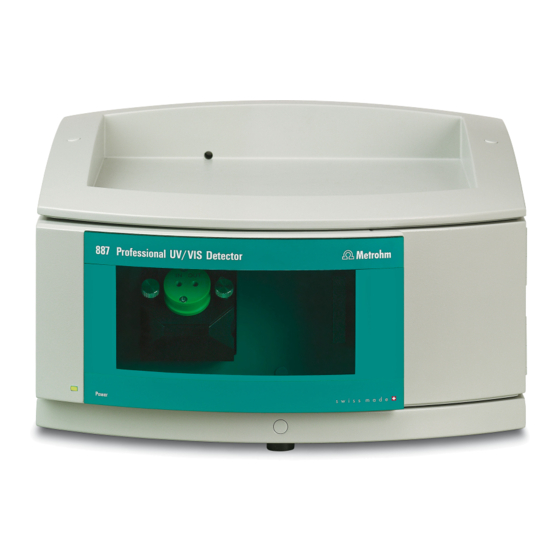
■■■■■■■■■■■■■■■■■■■■■■ 2.1 Front 2 Overview of the instrument Front Figure 1 Front Detector block Standby indicator ■■■■■■■■ 887 Professional UV/VIS Detector... -
Page 15: Rear
For connecting additional USB instruments. 11 USB 1 connection socket 12 PC connection socket For connecting additional USB instruments. For connecting the USB cable to the PC. 13 VIS connection socket For connecting the cable of the VIS lamp. ■■■■■■■■ 887 Professional UV/VIS Detector... -
Page 16: Installation
Proposed setup The 887 Professional UV/VIS Detector can be used as a detector with the instruments of the 850 Professional IC, the 881 Compact IC pro, and the 882 Compact IC plus family. For many applications with photometric detection, a post column reaction with the 886 Professional Thermostat / Reactor (2.886.0110) is required. -
Page 17: Figure 3 Proposed Setup
■ If you want to stack a 881 Compact IC pro or an 882 Compact IC plus instrument with a 887 Professional UV/VIS Detector, the 886 Professional Thermostat / Reactor and/or a 872 Extension Module, you will require the 6.2061.120 System Connector to adapt the different support surfaces. -
Page 18: Mounting Base Tray And Bottle Holder (Optional)
850 Profes- sional IC instrument: One or more 872 Extension Module. ■ An 886 Professional Thermostat / Reactor. ■ An 887 Professional UV/VIS Detector. ■ or another instrument of the same support surface. ■ 3.3.1 Removing / mounting the base tray The base tray must be removed, in case you want to place another instru- ment under the IC instrument. - Page 19 There are no loose parts in the instrument. ■ The instrument is lying on it side, and the bottom surface is visible. ■ To mount the base tray, you need a 3 mm hexagon key (6.2621.100). ■■■■■■■■ 887 Professional UV/VIS Detector...
-
Page 20: Removing / Mounting The Bottle Holder
The instrument is switched off. ■ The bottle holder is cleared. ■ Drainage tubing is disconnected from the drainage tubing connection ■ of the bottle holder. To remove the bottle holder, you need a 3 mm hexagon key (6.2621.100). ■■■■■■■■ 887 Professional UV/VIS Detector... - Page 21 Mounting the bottle holder Before you can mount the bottle holder, the following preconditions must be met: The instrument is switched off. ■ To mount the bottle holder, you need a 3 mm hexagon key (6.2621.100). ■■■■■■■■ 887 Professional UV/VIS Detector...
- Page 22 (see also the manual for the IC instrument). 5 If one of the instruments in the stack is equipped with a leak sensor connection socket, connect the leak sensor (see manual of the IC instrument). ■■■■■■■■ 887 Professional UV/VIS Detector...
-
Page 23: Capillary Connections In The Ic System
In order to keep the dead volume as low as possible, capillary connec- tions should generally be as short as possible. NOTICE For an improved overview, capillary and tubing connections can be bun- dled with the 6.1815.010 spiral band. ■■■■■■■■ 887 Professional UV/VIS Detector... - Page 24 Creating dead volume free capillary connections To create dead volume free capillary connections, proceed as follows: 1 Slide the pressure screw over the capillary. Ensure that the capillary protrudes 1–2 mm from the tip of the pressure screw. ■■■■■■■■ 887 Professional UV/VIS Detector...
-
Page 25: Installing The Flow-Through Cell
Figure 5 Cell block Cell holder Covering plate Holder for the flow-through cell. Protects the cell holder form contamination if no cell is installed. Knurled screws Cylinder screw For correct alignment of the flow-through cell ■■■■■■■■ 887 Professional UV/VIS Detector... - Page 26 In order to fix the flow-through cell in the correct position, both knurled screws must be tightened symmetrically and with constant force. Any tilting, twisting or canting of the flow-through cell influences the light incidence and thus the measuring results. ■■■■■■■■ 887 Professional UV/VIS Detector...
-
Page 27: Connecting The Flow-Through Cell
Slide the pressure screw over the detector inlet capillary such that ■ a small part of the capillary is visible at the top. Screw the detector outlet capillary to the detector outlet with the ■ pressure screw. ■■■■■■■■ 887 Professional UV/VIS Detector... -
Page 28: Connecting The Instrument
The instrument must be switched off when connecting the PC. 1 Connecting the USB cable Connect the PC connection socket of the instrument to a USB con- nector of the computer via the 6.2151.020 USB cable. ■■■■■■■■ 887 Professional UV/VIS Detector... -
Page 29: Connecting The Instrument To The Power Grid
Unplug the power plug immediately if you suspect that moisture has ■ gotten inside the instrument. Only personnel who have been issued Metrohm qualifications may ■ perform service and repair work on electrical and electronic parts. Connecting the power cord... -
Page 30: Start-Up
■■■■■■■■■■■■■■■■■■■■■■ 4 Start-up The 887 Professional UV/VIS Detector is set up together wit other instru- ments, e.g. an 850 Professional IC and the 886 Professional Thermostat/ Reactor. Putting the 887 Professional UV/VIS Detector into opera- tion 1 Start MagIC Net. -
Page 31: Figure 8 Intensity Spectrum Ok
Figure 8 Intensity spectrum ok If the intensity spectrum is cut off like the one in figure 9, then the lamp settings must be adjusted (see chapter 6.5, page 30). Figure 9 Intensity spectrum too high ■■■■■■■■ 887 Professional UV/VIS Detector... -
Page 32: Operation
■■■■■■■■■■■■■■■■■■■■■■ 5 Operation The instrument is operated via MagIC Net™ software only. Additional information on operating MagIC Net™ can be found in the document "Tutorial for MagIC Net™" or in the online help. ■■■■■■■■ 887 Professional UV/VIS Detector... -
Page 33: Operation And Maintenance
In such cases, the Metrohm Service must be informed. Spillages of chemicals and solvents should be cleaned up immediately. In particular, the plug connections on the rear panel of the instrument (espe- cially the mains plug) should be protected from contamination. -
Page 34: Shutting Down
Door CAUTION The door is made of PMMA (poly(methyl methacrylate)). It must never be cleaned with abrasive media or solvents. CAUTION Never hold the instrument by the door when lifting or moving it. ■■■■■■■■ 887 Professional UV/VIS Detector... -
Page 35: Replacing The Uv Lamp
Lamp module Lamp cooling element VIS lamp holder VIS lamp UV lamp Halogen lamp (6.2804.100) Deuterium-Lamp (6.2804.060) with operat- ing hours counter. Fastening ring For UV lamp. To replace the UV lamp, proceed as follows: ■■■■■■■■ 887 Professional UV/VIS Detector... - Page 36 Loosen the retaining ring of the UV lamp plug and pull the plug out of the UV connection socket. 2 Loosening the fastening ring Loosen and remove the fastening ring of the UV lamp. 3 Removing UV lamp Carefully remove the old UV lamp from its housing. ■■■■■■■■ 887 Professional UV/VIS Detector...
-
Page 37: Figure 12 Lamp Module - Without Uv Lamp
Clean the lamps surface with alcohol, if it is stained, before reinserting 1 Inserting the UV lamp Inset the new UV lamp (6.2804.060) into the opening for the UV lamp on the cooling element. ■■■■■■■■ 887 Professional UV/VIS Detector... -
Page 38: Replacing The Vis Lamp
Adjusting the lamp settings Before you can adjust the lamp settings, all the following preconditions must be unconditionally met: The UV lamp is burning for at least 30 minutes. ■ The flow-through cell is clean. ■ ■■■■■■■■ 887 Professional UV/VIS Detector... -
Page 39: Cleaning The Flow-Through Cell
1 Starting automatic lamp setting In MagIC Net™, go to the program part Configuration and ■ select the 887 UV/VIS Detector from the device table. Click Edit ▶ Properties... to open the properties window. ■ On the Detector tab, click on [Properties...] to open the detec- ■... - Page 40 15 minutes with ultrapure water to wash ■ away the dissolved deposits. 2 Observe the baseline during the last rinsing step. If the baseline remains flat, the flow-through cell is clean. ■■■■■■■■ 887 Professional UV/VIS Detector...
-
Page 41: Figure 13 Flow-Through Cell - Parts
1 Removing the flow-through cell Disconnect inlet capillary and outlet capillary, ■ Loosen the knurled screws and remove them, ■ Remove the flow-through cell from the cell holder. ■ Figure 13 Flow-through cell – parts Retaining screw Outer seal ■■■■■■■■ 887 Professional UV/VIS Detector... - Page 42 5 Cleaning the second lens Repeat steps 2 – 4 at the opposite side of the cell holder. 6 Re-inserting the flow-through cell Follow steps 3 – 4 of "Installing the flow-through cell", page 18. ■■■■■■■■ 887 Professional UV/VIS Detector...
-
Page 43: Troubleshooting
(use PEEK capillaries with an internal diameter chromatogram. of 0.25 mm between the injection valve and Splitting (dual detector). peaks) Lamp does not Lamp defective. Replace UV lamp (see chapter 6.3, page 27). ignite. ■■■■■■■■ 887 Professional UV/VIS Detector... -
Page 44: Technical Specifications
Accuracy, abso- ±3 nm lute Stability ±1 nm (across temperature range) Optical resolu- 5 nm (at 254 nm) tion Measuring interval Data rate for 0.5 - 50 samples/sec each channel ■■■■■■■■ 887 Professional UV/VIS Detector... -
Page 45: Lamps
RS-232 commands. Lamps UV lamp Type (deuterium) Power con- approx. 20 - 30 W sumption Service life approx. 1,000 h VIS lamp Type Halogen Power con- approx. 5 W sumption Service life approx. 10,000 h ■■■■■■■■ 887 Professional UV/VIS Detector... -
Page 46: Ambient Conditions
UL94V0, CFC-free, coated material Controls Indicators LED for standby indicator On/off switch On the rear of the instrument Mains connection Required voltage 100…240 V (±10%) Required fre- 50…60 Hz quency Power consump- 105 VA tion ■■■■■■■■ 887 Professional UV/VIS Detector... -
Page 47: Accessories
Downloading the accessories list 1 Enter https://www.metrohm.com/ into your Internet browser. 2 Enter the article number (e.g. 2.887.0010) into the search field. The search result is displayed. 3 Click on the product. Detailed information regarding the product is shown on various tabs. -
Page 48: Index
Electrostatic charge ....4 Pressure screws VIS lamp Connection ......15 Replacing ......30 Voltage ........38 flow-through cell ...... 17 Installing ......18 Reference conditions ....36 Flow-through cell Regeneration ......25 Cleaning ......31 ■■■■■■■■ 887 Professional UV/VIS Detector...
Need help?
Do you have a question about the 887 and is the answer not in the manual?
Questions and answers