
Subscribe to Our Youtube Channel
Related Manuals for Metrohm IC Conductivity Detector


Summary of Contents for Metrohm IC Conductivity Detector
- Page 1 IC Professional Detector IC Conductivity Detector Manual 8.850.8057EN / 2019-09-23...
- Page 3 Metrohm AG CH-9100 Herisau Switzerland Phone +41 71 353 85 85 Fax +41 71 353 89 01 info@metrohm.com www.metrohm.com IC Professional Detector IC Conductivity Detector 2.850.9010 Manual 8.850.8057EN / 2019-09-23...
- Page 4 Technical Communication Metrohm AG CH-9100 Herisau techcom@metrohm.com This documentation is protected by copyright. All rights reserved. This documentation has been prepared with great care. However, errors can never be entirely ruled out. Please send comments regarding possible errors to the address above.
-
Page 5: Table Of Contents
4 Operation and maintenance Maintenance ............... 15 5 Troubleshooting Problems and their solutions ..........16 6 Technical specifications Conductivity measuring system ........17 Interfaces ................18 Energy supply ..............18 Reference conditions ............18 Dimensions ................18 ■■■■■■■■ 2.850.9010 IC Conductivity Detector... - Page 6 ■■■■■■■■■■■■■■■■■■■■■■ Table of contents 7 Accessories Index ■■■■■■■■ 2.850.9010 IC Conductivity Detector...
- Page 7 Rear ....................3 Figure 3 Inserting the detector ................ 8 Figure 4 Connection detector – separation column ........11 Figure 5 Connector detector – MSM ............. 12 Figure 6 Connection detector – MCS ............12 ■■■■■■■■ 2.850.9010 IC Conductivity Detector...
-
Page 9: Introduction
– Digital Signal Processing). The conductivity detector exhibits outstanding thermal stability and thus guarantees reproducible measuring conditions. The IC Conductivity Detector can only be used together with the IC instru- ment. The software MagIC Net automatically recognizes the IC Conduc- tivity Detector and checks its functional readiness. -
Page 10: Overview Of The Instrument
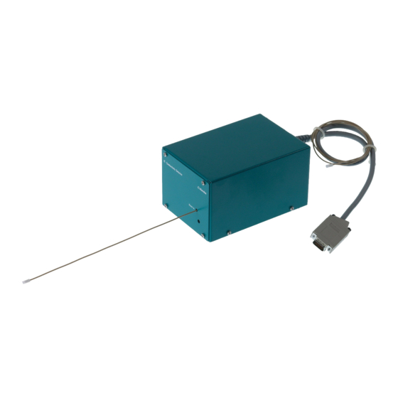
■■■■■■■■■■■■■■■■■■■■■■ 1.2 Overview of the instrument Overview of the instrument 1.2.1 Front Figure 1 Front IC detector 2.850.9010 Opening for temperature sensor Detector inlet capillary Permanently installed. ■■■■■■■■ 2.850.9010 IC Conductivity Detector... -
Page 11: Rear
Type plate With serial number. Intended use The IC Conductivity Detector can only be used together with an IC instru- ment. It is used for the precise measurement of the conductivity during the ion chromatographic determination of cations and anions. -
Page 12: About The Documentation
Warning This symbol draws attention to a possible biological hazard. Caution This symbol draws attention to a possible damage of instruments or instrument parts. Note This symbol marks additional information and tips. ■■■■■■■■ 2.850.9010 IC Conductivity Detector... -
Page 13: Safety Instructions
1.5.2 Electrical safety WARNING Only personnel qualified by Metrohm are authorized to carry out service work on electronic components. WARNING Never open the housing of the instrument. The instrument could be damaged by this. There is also a risk of serious injury if live components are touched. -
Page 14: Working With Liquids
The correct disposal of your old instrument will help to prevent negative effects on the environment and public health. More details about the disposal of your old instrument can be obtained from your local authorities, from waste disposal companies or from your local dealer. ■■■■■■■■ 2.850.9010 IC Conductivity Detector... -
Page 15: Installation
2.1.3 Location The IC Conductivity Detector is designed for usage in the detector cham- ber of the IC instruments. For the location, the same conditions apply as for the IC instrument. -
Page 16: Figure 3 Inserting The Detector
■■■■■■■■■■■■■■■■■■■■■■ 2.2 Inserting the detector Figure 3 Inserting the detector Detector connection cable Detector outlet capillary ■■■■■■■■ 2.850.9010 IC Conductivity Detector... - Page 17 5 Tightening the knurled screws Optional with 850 instruments: Reattach the handle higher up ■ and use it as a holder for MPaks. Tighten the knurled screws. ■ ■■■■■■■■ 2.850.9010 IC Conductivity Detector...
-
Page 18: Connecting The Detector
The detector outlet capillary must be free of blockages (the mea- suring cell is tested to 5 MPa = 50 bar backpressure). NOTICE The detector outlet capillary must not be shortened! Shortening the detector outlet capillary leads to increased noise! ■■■■■■■■ 2.850.9010 IC Conductivity Detector... -
Page 19: Connecting The Detector Inlet Capillary
Fasten the detector inlet capillary (4-1) on the output of the col- ■ umn (4-3) using a 6.2744.070 pressure screw (4-2). Figure 4 Connection detector – separation column Detector inlet capillary PEEK pressure screw, short 6.2744.070 Separation column ■■■■■■■■ 2.850.9010 IC Conductivity Detector... -
Page 20: Figure 5 Connector Detector - Msm
Fasten the detector inlet capillary (6-1) using a 6.2744.090 long ■ PEEK pressure screw (6-2) on the output of the MCS (6-3). Figure 6 Connection detector – MCS Detector inlet capillary Pressure screw, long 6.2744.090 MCS output ■■■■■■■■ 2.850.9010 IC Conductivity Detector... -
Page 21: Connecting The Instrument To The Power Grid
Unplug the power plug immediately if you suspect that moisture has ■ gotten inside the instrument. Only personnel who have been issued Metrohm qualifications may ■ perform service and repair work on electrical and electronic parts. Connecting the power cord... -
Page 22: Start-Up
■■■■■■■■■■■■■■■■■■■■■■ 3 Start-up The IC Conductivity Detector is put into operation together with the IC instrument in which it has been inserted to. Additional information can be found in the Start-up chapter in the manual for the IC instrument. ■■■■■■■■... -
Page 23: Operation And Maintenance
If this does not help, the conductivity detector can be rinsed against the normal flow direction. For this, connect the high pressure pump to the detector outlet capillary (2-2) and rinse - the pressure may not exceed 5 MPa. ■■■■■■■■ 2.850.9010 IC Conductivity Detector... -
Page 24: Troubleshooting
Rinse detector against the normal flow ■ direction. Conductivity detec- No connection. Check the connection of the detector ■ tor is not recognized cable. in the software Switch the instrument off and on again ■ (after 15 seconds). ■■■■■■■■ 2.850.9010 IC Conductivity Detector... -
Page 25: Technical Specifications
5.0 MPa (50 bar) ating pressure Cell tempera- 20 - 50 °C in increments of 5 °C ture Temperature < 0.001 °C stability Temperature 0 - 5%/K adjustable, default 2.3%/K compensation Heating time < 30 minutes (40 °C) ■■■■■■■■ 2.850.9010 IC Conductivity Detector... -
Page 26: Interfaces
Reference conditions Ambient tempera- 25 °C (±3 °C) ture Instrument status > 40 min in operation Dimensions Width 108 mm Height 93 mm Depth 158 mm Weight (without 1.858.9010: 2.3 kg accessories) Material Housing Steel, coated ■■■■■■■■ 2.850.9010 IC Conductivity Detector... - Page 27 The PDF file with the accessories data is created. NOTICE Once you have received your new product, we recommend download- ing the accessories list from the Internet, printing it out and keeping it together with the manual for reference purposes. ■■■■■■■■ 2.850.9010 IC Conductivity Detector...
- Page 28 Technical specifications ..18 Dimensions ......18 Detector outlet capillary ..10 Energy supply ..... 18 Interfaces ......18 Measuring range ...... 17 Reference conditions ..18 Detector Cable connector ....10 Noise ........17 Placing ......... 7 ■■■■■■■■ 2.850.9010 IC Conductivity Detector...
Need help?
Do you have a question about the IC Conductivity Detector and is the answer not in the manual?
Questions and answers