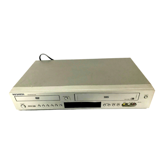
Page 3
CONTENTS 5. TroubleShooting 5-1 ~ 5-34 6. Exploded View and Parts List 6-1 ~ 6-10 6-1 Cabinet Assembly (6-2) 6-2 VCR Mechanical Parts (Top Side) (6-4) 6-3 VCR Mechanical Parts (Bottom Side) (6-6) 6-4 DVD Mechanical Parts (6-8) 7. Electrical Parts List 7-1 ~ 7-14 8.
Page 4
CONTENTS 11-9 OSD/VPS/PDC (11-10) 11-10 TM (11-11) 11-11 I/O (11-12) 11-12 DVD A/V Codec & Memory Interface (11-13) 11-13 DVD RF & Servo (11-14) 11-14 DVD Video Output (11-15) 11-15 B/B Connector & Power Connection (11-16) 12. Operating Instructions and Installation 12-1 ~ 12-60 13.
Page 5
CONTENTS 14-1 ~ 14-26 14. VCR Deck Operating Description 14-1 Features of Mechanism (14-1) 14-2 Basic Configuration of Mechanism (14-1) 14-3 Main Mechanism and Functions (14-2) 14-4 Basis of the Mechanism (14-4) 14-5 System Control (14-9) 14-6 System Control and Mechanical Operations (14-10)
Metal Part cal return path to the chassis. Any current measured must not exceed 0.5mA. Reverse the instrument power cord plug in the out- ohmmeter let and repeat the test. See Fig. 1-1. Fig. 1-2 Insulation Resistance Test Samsung Electronics...
Page 7
(5) antenna wiring. Always inspect in all areas tinuously and new instructions are issued whenev- for pinched, out-of-place, or frayed wiring, Do not er appropriate. change spacing between a component and the printed-circuit board. Check the AC power cord for damage. Samsung Electronics...
Components identi- fied by shading, by( ) or by ( ) in the circuit dia- gram are important for safety or for the characteris- tics of the unit. Always replace them with the exact replacement components. Samsung Electronics...
(6) Do not remove a replacement ESD device from its protective package until immediately before your are ready to install it.(Most replacement ESD devices are packaged with leads electrically short- ed together by conductive foam, aluminum foil or comparable conductive materials). Samsung Electronics...
◆ Be sure to put on a wrist strap grounded to the sheet. ◆ Be sure to lay a conductive sheet made of copper etc. Which is grounded to the table. Samsung Electronics...
3) Make solder land 2 points short on Pick-up. (See Fig. 1-4) 4) Disassemble the Pick-up. Note : If the assembly and disassembly are not done in correct sequence, the Pick-up may be damaged. PICK-UP ASS'Y SOLDER LAND 2 POINTS SHORT Fig. 1-4 Samsung Electronics...
Page 12
Tension post Tape sensor Tape loading Reel brake REC-inhibiting SW Pinch lever Idle gear Cassette holder Loading motor cam gear Reel sensor (Front loading setion) (Loading motor drive section) (Front loading setion) Fig. 14-1 Basic Configuration of Mechanism Samsung Electronics 14-1...
Page 13
Cylinder T slant guide S slant guide ACE head Tension post Capstan No.9 guide Pinch roller FE head No.8 guide T guide roller S guide roller show the locations to be adjusted. Fig. 14-3 Guide Path System 14-2 Samsung Electronics...
Page 14
No. 8 guide Pinch roller Cylinder Capstan No. 9 guide Tape guide Tension post Tape guide S (Supply) reel disc Idle gear Capstan belt Clutch gear (Clutch mechanism) T (Tape-up) reel disc Fig. 14-4 Reel Drive System Samsung Electronics 14-3...
Page 15
(9) When the cassette is out, the reverse steps of the above procedure are carried out. Cassette Loading Complete Tape Loading Full Loading Mode Fig. 14-5 Loading motor FL arm lever FL drive slider FL camgear Worm wheel Fig. 14-6 Drive Transmission Path 14-4 Samsung Electronics...
Page 16
FE head Pinch roller Cylinder Capstan No. 9 guide Tape guide S guide roller Tape guide S (Supply) reel disc Idle gear Capstan belt Clutch gear (Clutch mechanism) T (Tape-up) reel disc Fig. 14-7 Cassette IN/OUT Mode Samsung Electronics 14-5...
Page 17
In this case, tape tension applied to the cylinder is decreased to protect the tape and to prevent the tape from scratches. 14-6 Samsung Electronics...
Page 18
FE head No. 8 guide Pinch roller Cylinder Capstan No. 9 guide Tape guide Tension post Tape guide S (Supply) reel disc Idle gear Capstan belt Clutch gear (Clutch mechanism) T (Tape-up) reel disc Fig. 14-9 FF/REW Mode Samsung Electronics 14-7...
Page 19
FE head No. 8 guide Pinch roller Cylinder Capstan No. 9 guide Tape guide Tension post Tape guide S (Supply) reel disc T (Tape-up) reel disc Clutch gear (Clutch mechanism) Capstan belt Idle gear Fig. 14-10 Record/Playback Mode 14-8 Samsung Electronics...
Page 20
FG pulse CTL pulse (Linear time counter) AUDIO Control IIC BUS VIDEO REC control TUNER Cylinder motor control Cylinder Cylinder motor motor drive POWER ON/OFF REC mute FG/PG pulse TV/VCR Fig. 14-11 System Control Block Diagram Samsung Electronics 14-9...
Page 21
The mechanism operates as shown in Fig. 14-13 according to the timing chart in Fig. 14-14. Note : The Switch Detect is actuated by the rotational moving of Lever FL Arm-R and Switch on or off by insertion or ejection of a cassette. 14-10 Samsung Electronics...
Page 22
T loading lever assembly S loading lever assembly Loading motor Loading drive gear FL cam gear Joint gear 1 Cam slider T brake S brake Pinch drive lever Tension drive lever Joint gear 2 Fig. 14-13 Mechanical Operation Samsung Electronics 14-11...
Page 24
- S BRAKE is detached from S REEL DISC completely. So S REEL DISC is free. Fig. 14-15 2) SOFT BRAKE(during LOADING, STOP 1, FF/REW 1) - The small load is given to S REEL DISC. Fig. 14-16 Samsung Electronics 14-13...
Page 25
- T BRAKE is detached from T REEL DISC completely. So T REEL DISC is free. Fig. 14-18 2) SOFT BRAKE (UNLOADING Completion ,STOP 1, FF/REW 2 ) - The small load is given to T REEL DISC. Fig. 14-19 14-14 Samsung Electronics...
Page 26
Reference Information 3) REVERSE SEARCH BRAKE (RPS) - The medium load is given to T REEL DISC. Fig. 14-20 4) MAIN BRAKE (on the loading, STOP 2) - The large load is given to T REEL Fig. 14-21 Samsung Electronics 14-15...
Page 27
The circuit configuration of the mode sensor drive is shown in Fig. 14-22. CN604 Load (+) IC601 CAPSTAN MOTOR L.M B+ Loading motor DRIVE IC L,M CTL 58 Load (-) AL 5V LM F/R AL 5V SW603 Mode SW Fig. 14-22 Mode Sensor Drive 14-16 Samsung Electronics...
Page 28
After 300msec the loading motor rotates in the forward direction and enters the tape loading operation. T slider assembly S slider assembly No. 9 guide lever Tension arm T brake (soft) S brake (off) Idle lever assembly Fig. 14-23 Cassette-Loading Mode (Position I) Samsung Electronics 14-17...
Page 29
ˇ The tension post touches the tape, band brake force is applied, and the tension servo brake mechanism actuates. ¨ Brakes for the reel discs are all off. T slider assembly S slider assembly Tension lever No. 9 guide lever T brake (soft) S brake (off) Fig. 14-24 Tape Loading Operation (Position II) 14-18 Samsung Electronics...
Page 30
(2) IC601 makes the loading motor stop after 200ms passed from sensing “OFF”. (3) Also IC601 makes the loading motor rotate in the forward direction after 120ms passed. (4) IC601 makes the loading motor stop after 100ms passed from loading motor rotating in the forward direction. Samsung Electronics 14-19...
Page 31
4) The S, T soft brakes are being applied. T slider assembly Pinch assembly (off) S slider assembly Tension lever (off) T brake (soft) S brake (off) Fig. 14-25 Stop Mode (Position V) 14-20 Samsung Electronics...
Page 32
IV (playback mode), thus setting the playback standby mode. T slider assembly Pinch assembly (OFF) Tension lever (OFF) No. 9 guide lever (OFF) S brake (OFF) T brake (soft brake) Fig. 14-26 FF/REW 2 Mode (Position VII) Samsung Electronics 14-21...
Page 33
(6) The recording speed data identified by IC601 is displayed in the Led module. Pinch assembly (ON) Tension lever (ON) No. 9 guide lever (OFF) S brake (OFF) T brake (OFF) Fig. 14-27 Playback Mode (Position IV) 14-22 Samsung Electronics...
Page 34
The tape is taken up at a constant torque by the clutch mechanism. (The mechanical operation is the same as that in the playback mode.) (4) The recording speed data identified by IC601 is displayed on the Led module. Samsung Electronics 14-23...
Page 35
(5) The recording speed data identified by IC601 is displayed on the Led module. Pinch assembly (ON) Tension lever (OFF) No. 9 guide lever (ON) S brake (OFF) T brake (RPS brake) Fig. 14-28 RPS Mode (Position III) 14-24 Samsung Electronics...
Page 36
(3) After completion of the rewinding for synchronous editing, the cam slider is in the position IV (playback mode), the cylinder motor is rotating, and the capstan motor and the loading motor stop. Samsung Electronics 14-25...
Page 37
Reference Information MEMO 14-26 Samsung Electronics...
2-3 Option Product Specification Remark Description Parts No Description Fig STANDBY/ON OPEN/ C LOSE Model standard Remote Control AK59-00008D of DVD-V5450/XEC Model standard Batteries for Remote Control of DVD-V5450/XEC AC43-12002H S.N.A Model standard Owner s Instructions AK68-00646E of DVD-V5450/XEC AC39-22017Z Model standard Audio &...
Page 42
This can be virtually used as hard-disk, with a random DVD-RAM (more than 100,000times) read-write access Rewritable Similar to DVD-RAM except than its technology features DVD-RW (About 1000times) a separated read-write access more like phonograph than a hard disk. Samsung Electronics...
Recording type Dolby Digital Linear PCM MPEG-1 Layer 2 AUDIO Transmission rate 448Kbps/stream 6.144Mbps/stream 224Kbps 1 Analog CH. Channel 5.1CH/stream 8CH/stream 1 Stream of Dolby Digital 2 Digital CH. (16Bit/44.1KHz) Sampling frequency 48KHz 16, 20, 24Bit/48, 96KHz 16Bit/44.1KHz Samsung Electronics...
Page 44
Data loss and enables efficient compression. Loss area • MPEG-1 (Fixed compression : Max. 1/140) Amount of data • Frame unit compression. • Compresses all data using the same ratio. Video-CD - Fast movements are jagged, and unnatural Time Samsung Electronics...
Page 45
• Various Digital Recordings are possible as shown in the table to the right. Sampling Frequency Bit Rate 16bit 48KHz 20bit 24bit 16bit 96KHz 20bit 24bit • Dolby Digital compatible Audio Mode Channel Format Audio Coding Front Surround (Rear) Remark Mode Mono Stereo Mono Mono Surround Samsung Electronics...
Page 46
• Up to 9 angles of view may be stored, enabling the viewer to select a specific viewpoint at a given time. --> Especially, for the Music Video and Sports Title, this provides a more lively image of the scene. Note ; This function is disc-dependent, may not work on all DVDs. Samsung Electronics...
Page 47
• Region 6 : China. • Region 0 : Worldwide (All Code) ˆ Œ ´ Œ Ø ´ Œ ˇ ˆ ¨ ´ ¨ • Adoptation of the Macrovision System disables the copying on to other media. Samsung Electronics 2-10...
Page 48
• Different Authoring Process are used accoring to the Software developers, and this may affect the DVD image quality. • Authoring Process bit stream Video/Audio MPEG-2 Master Encoding Disc Production bit stream Video/Audio Surround Audio AC-3/MPEG Audio Cutting Subtitle Master Encoding Master Multiplexing bit stream Subtitle Subtitle Master Encoding Authoring Process Samsung Electronics 2-11...
Page 50
12. FRONT PANEL DISPLAY STANDBY/ON BUTTON 13. PROGRAMME SELECTION BUTTON REWIND/SKIP BACK BUTTON 14. DVD/VCR SELECT BUTTON STOP BUTTON 15. PROGRESSIVE SCAN MODE BUTTON PLAY/STILL BUTTON 16. AUX VIDEO INPUT JACK 17. AUX AUDIO L, R INPUT JACK Samsung Electronics 12-1...
Page 51
2. A DVD, CD or SVCD is loaded. 3. The time, counter position, time remaining or current deck status is displayed. 4. VHS tape is inserted. 5. The VCR Deck is active. 6. A Timer Recording is programmed or in progress. English - 7 Samsung Electronics 12-2...
Page 52
Operating Instructions Accessories Inserting Batteries in the Remote Control You have just purchased a SAMSUNG Video Cassette You must insert or replace the batteries in the remote Recorder (DVD-VCR). control when you: Together with your DVD-VCR, you will find the following •...
Page 53
Used to allow the repeat play a title, chapter, … † 6. TRK track, disc or A-B. Used to adjust picture alignment manually to obtain the best possible picture during playback. 7. AUDIO Used to access various audio functions. English - 9 Samsung Electronics 12-4...
Page 54
Other Equipment ....12 • Plug & Auto Set up ....13 10 - English Samsung Electronics 12-5...
Page 55
DVD-VCR. Plug the other end of the audio cable into the appropriate input connectors on your Hi-Fi Aerial stereo system. Aerial RF cable RF cable English - 11 Samsung Electronics 12-6...
Page 56
36, which is used by the DVD-VCR, e.g. re-adjust to channel 33. Aerial SCART Cable Satellite Receiver or other Equipment RF cable Aerial Connector SCART Cable RF cable 12 - English Samsung Electronics 12-7...
Page 57
So if you want to change this fixed RETURN MENU one, you can change. (refer to “Presetting the Stations Automatically” on page 17) Start the auto setup. Auto Set Up will be started. Check antenna and TV cable connection. RETURN MENU English - 13 Samsung Electronics 12-8...
Page 58
(B/G-G/K) ......21 • Setting the VCR Output Channel ..21 14 - English Samsung Electronics 12-9...
Page 59
RETURN MENU users to change the TV setup to the standard resolution output. Please contact our service center if there is any problem in the compatibility of the product's progressive output with TV. English - 15 Samsung Electronics 12-10...
Page 60
Clock Set Language Set SETUP √ English Time Date Year Français 12 : 00 01 / FEB / 2005 TUE Deutsch Auto Clock : On Español Italiano PROG Nederlands FUNC RETURN MENU MENU RETURN 16 - English Samsung Electronics 12-11...
Page 61
√ TV System √ VCR Output CH :CH36 Please Wait PROG √ √ FUNC RETURN MENU RETURN MENU • If you wish to cancel the auto scanning before the end, press the MENU button. English - 17 Samsung Electronics 12-12...
Page 62
: - - - Install √ Auto Setup SETUP NAME : - - - - √ Manual Setup √ TV System √ VCR Output CH :CH36 …† œ √ MEMORY : OK RETURN PROG FUNC RETURN MENU 18 - English Samsung Electronics 12-13...
Page 63
Press the … or † button to select required preset TV station. Press the CLEAR button to delete. Repeat the same procedure from step 4 onwards until all the required stations have been cleared. English - 19 Samsung Electronics 12-14...
Page 64
MENU Press the OK or √ button. The TV STATION TABLE menu is displayed. TV STATION TABLE NAME - - - - - - - …† √ SWAPPING : OK DELETE : CLEAR RETURN 20 - English Samsung Electronics 12-15...
Page 65
: CH36 Then tune your television again (see page 14). PROG FUNC Install RETURN MENU √ SETUP Auto Setup √ Manual Setup √ TV System √ VCR Output CH : CH36 PROG FUNC RETURN MENU English - 21 Samsung Electronics 12-16...
Page 66
• Checking a Preset Recording ... . 35 FUNC • Cancelling a Preset Recording ... 36 RETURN MENU 22 - English Samsung Electronics 12-17...
Page 67
Colour System : Auto SETUP User Set √ NICAM : On √ Colour System : Auto SETUP √ : On √ NICAM : On √ : On PROG PROG FUNC RETURN MENU FUNC RETURN MENU English - 23 Samsung Electronics 12-18...
Page 68
User Set √ NICAM : On √ Auto Power Off : Off √ : On PROG √ Screen Messages : On √ ShowView Extend : Off FUNC PROG RETURN MENU FUNC RETURN MENU Note 24 - English Samsung Electronics 12-19...
Page 69
: English SETUP √ Repeat Play : Off √ Clock √ Install √ User Set √ Auto Power Off : Off PROG PROG √ Screen Messages : On FUNC FUNC RETURN MENU RETURN MENU English - 25 Samsung Electronics 12-20...
Page 70
240 mins. or 4 hours E240 260 mins. or 4 hours and 20 mins. E260 VCR Setup √ Tape Select : E180 300 mins. or 5 hours SETUP E300 √ Repeat Play : Off PROG FUNC RETURN MENU 26 - English Samsung Electronics 12-21...
Page 71
(created by a broken safety tab) is overed with adhesive tape. • If you reach the end of the tape while recording, the cassette rewinds automatically. English - 27 Samsung Electronics 12-22...
Page 72
Hold down the REC ( ) button for a while to start recording. The record indicator appears on the television screen and DVD-VCR display. An index is recorded on the tape (refer to page 37). 28 - English Samsung Electronics 12-23...
Page 73
√ SETUP Standard √ ShowView PR Day Start Stop Speed 1 WE 1 13 : 25 19 : 57 PROG -- -- -- -- : -- -- : -- FUNC RETURN MENU RETURN MENU English - 29 Samsung Electronics 12-24...
Page 74
VPS/PDC. If you do set V/P to On, then you must set up the start-time exactly according to the published TV schedule. Otherwise the timer recording won’t take place. 30 - English Samsung Electronics 12-25...
Page 75
• W-SA : Weekly Saturday PROG FUNC PR Day Start Stop Speed RETURN MENU 1 WE 1 13 : 25 19 : 57 -- -- -- -- : -- -- : -- RETURN MENU English - 31 Samsung Electronics 12-26...
Page 76
• Auto SP (Standard Play) LP (Long Play) PR Day Start Stop Speed 1 WE 1 13 : 25 19 : 57 -- -- -- -- : -- -- : -- RETURN MENU 32 - English Samsung Electronics 12-27...
Page 77
* DVD-V5500 Timer Method SETUP If you want to set the timer program, press the OK key. PROG FUNC RETURN MENU * DVD-V6500 Timer Method √ Standard SETUP √ ShowView PROG FUNC RETURN MENU English - 33 Samsung Electronics 12-28...
Page 78
-- -- -- -- : -- -- : -- If you want to set the timer program, press the OK key. PROG FUNC RETURN MENU RETURN MENU * DVD-V6500 Timer Method √ Standard SETUP √ ShowView PROG FUNC RETURN MENU 34 - English Samsung Electronics 12-29...
Page 79
Cable ......41 • Using the Assemble Edit Function ..42 • Recording from Another VCR or Camcorder . . 42 English - 35 Samsung Electronics 12-30...
Page 80
SLOW SLOW PLAY PLAY PLAY function for more than about two minutes, the PLAY PLAY PLAY MOTION MOTION PLAY STILL DVD-VCR will automatically play to protect the: X1/10 X1/5 - Cassette - Video heads 36 - English Samsung Electronics 12-31...
Page 81
Intro Scan Press the OK or √ button. Press the … or † button to select VCR Function. PROG FUNC Function RETURN MENU √ DVD Function SETUP √ VCR Function PROG FUNC RETURN MENU English - 37 Samsung Electronics 12-32...
Page 82
Index mark. To cancel an Index search simply press the √ button. INTRO SCAN : œœ -06 If you want to watch the tape from a particular Index, press the √ button. 38 - English Samsung Electronics 12-33...
Page 83
• Twice to display the counter only • Three times to display the time remaining on the cassette • Four times to clear the display Hi-Fi audio system Camcorder English - 39 Samsung Electronics 12-34...
Page 84
When you have finished recording, press the button on both VCR and DVD-VCR. button. • If you wish to view the cassette being copied, your DVD-VCR must be connected as usual to the television (refer to page for further details). 40 - English Samsung Electronics 12-35...
Page 86
Press the OK or √ button again. Press the … or † button to select Audio. MENU RETURN Language Setup √ Disc Menu : English √ Audio : English √ Subtitle : Automatic MENU RETURN 42 - English Samsung Electronics 12-37...
Page 87
MENU Press the OK or √ button again. Press the … or † button to select Subtitle. Language Setup √ Disc Menu : English √ Audio : English √ Subtitle : Automatic MENU RETURN English - 43 Samsung Electronics 12-38...
Page 88
√ : Off √ Decoder. Dynamic Compression : On √ PCM Down Sampling : On Dynamic Compression RETURN MENU • Off : To select dynamic compression. • On : To select the standard range. 44 - English Samsung Electronics 12-39...
Page 89
√ 4:3 Letter Box DVD Setup √ SETUP Language Setup √ Audio Setup 4:3 Pan Scan √ Display Setup √ Parental Setup : 16:9 Wide √ DivX(R) Registration PROG FUNC RETURN MENU RETURN MENU English - 45 Samsung Electronics 12-40...
Page 90
RETURN MENU Press the OK or √ button to select the required option. Black Level : Off / On NTSC Disc Output : NTSC / PAL60 DVD Out : RGB / S-Video / Video 46 - English Samsung Electronics 12-41...
Page 91
Press the OK or √ button. The Use Password menu is displayed. Parental Setup Parental Setup √ Use Password : Yes √ √ Use Password : No Rating Level √ Change Password RETURN MENU RETURN MENU English - 47 Samsung Electronics 12-42...
Page 92
• How to make the DVD menu disappear or return to menu screen during set up; Press the RETURN or œ button. • If you have forgotten your password, refer to Forget Password in the Troubleshooting Guide. 48 - English Samsung Electronics 12-43...
Page 93
Registration. Samsung DVD+VCR Combo player with DivX Playback can only support English Subtitle. If you have any question or any problem, please DVD Setup feel free to contact your nearest SAMSUNG √ SETUP Language Setup Service Center and agency. √...
Page 94
When you have finished recording, press the button on both VCR and DVD-VCR. button. • If you wish to view the cassette being copied, your DVD-VCR must be connected as usual to the television (refer to page for further details). 40 - English Samsung Electronics 12-45...
Page 95
• Use whichever connection is available on your A/V Receiver. The display can be changed depend on its Version and without any notice. Note To Digital Audio Input of an A/V Receiver with a Dolby Digital Decoder English - 51 Samsung Electronics 12-46...
Page 96
) will jump to the next chapter/track. œœ) will jump to the beginning of the • Skip Back ( current chapter/track. œœ button again to jump to the • Press the beginning of the previous chapter/track. 52 - English Samsung Electronics 12-47...
Page 97
Select Chapter or Track Press the …/†, œ/√ buttons to select Chapter or Track, then press the OK button to change among all available chapters or tracks on the disc. English - 53 Samsung Electronics 12-48...
Page 98
The top, bottom, left and right of the screen are screen are cut off and the central portion of the cut off and the central portion of the screen is screen is enlarged. enlarged. 54 - English Samsung Electronics 12-49...
Page 99
The default is Off. Activate Subtitles Select an Angle option Press the œ or √ button to select On. Press the œ or √ button to select a camera angle you may wish to see. English - 55 Samsung Electronics 12-50...
Page 100
A - B Track Disc segment you want to repeat (Point A). The B is selected. • The minimum A-B Repeat time is 5 seconds. Chapter Title A - B A - B Chapter Title 56 - English Samsung Electronics 12-51...
Page 101
Press the œ or √ button to select Title. Press the OK button to repeat the title. Chapter Title A - B A - B Chapter Title VCD/CD Stereo VCD/CD Chapter Title A - B A - B Track Disc English - 57 Samsung Electronics 12-52...
Page 102
• Press the œ or √ button to move to a previously set bookmark. • Press the √ll button to play the mark. • Press the CLEAR button to cancel the mark. • Press the MARK button again to exit the mark menu. 58 - English Samsung Electronics 12-53...
Page 103
MP3 format, of at least 128Kbps and up to 160Kbps. However, choosing higher rates, like 192Kbps or more, only rarely give better sound quality. Conversely, files with decompression rates below 128Kbps will not be played properly. English - 59 Samsung Electronics 12-54...
Page 104
Press the OK button. The selection numbers are displayed in the Program Order box. PROGRAM 01 ROOT Program Order RETURN CLEAR Press the √ll button. The disc will be played in programmed order. 60 - English Samsung Electronics 12-55...
Page 105
Press the œ or √ button to select Note disappear. Press the DISC MENU button on Each time the OK button is pressed, the picture is enlarged up to 4X. the remote control to display the menu again. (Normal Normal) RETURN English - 61 Samsung Electronics 12-56...
Page 106
• If a number of folders in 1 Disc is over 300, only JPEG files in 300 folders can be played. Timer : RETURN • Depending on the file size, each interval between images may take longer or shorter than the manual suggests. 62 - English Samsung Electronics 12-57...
Page 107
1/8, 1/4 or 1/2 normal speed. If the file resolution is small, it scales up to 2 times • Audio is muted during slow motion playback. automatically. So you can see the more larger screen. • English - 63 Samsung Electronics 12-58...
Page 108
MP3s encoded at bitrates from 80kbps to 320kbps, AC3s from 128kbps to 448kbps, and WMAs from 56kbps to 160kbps are supported. • In addition, for subtitles, Samsung will support Text format (SMI). If the "Codec. Not Supported" message is displayed, the selected file cannot be played back.
Page 111
4-1-6 VCR Main PCB Removal Œ REMOVE 4 SCREWS When installing the ass'y full deck on the Main PCB, be sure to align the assembly point of mode switch. MODE SWITCH ASSEMBLY POINT Fig. 4-6 VCR Main PCB Removal Samsung Electronics...
Page 113
4-3-1 Top View ´ Œ ˇ ¨ Ø ˆ Fig. 4-8 Top parts Location-1 Œ GEAR FL CAM ´ MOTOR LOADING ASS’Y ˇ LEVER FL ARM ASS’Y ¨ HOLDER FL CASSETTE ASS’Y ˆ LEVER FL DOOR Ø SLIDER FL DRIVE Samsung Electronics...
Page 114
´ CYLINDER ASS’Y ˝ GEAR IDLE ˇ ACE HEAD ASS’Y Ô LEVER IDLE ¨ LEVER UNIT PINCH ASS’Y LEVER T BRAKE ASS’Y ˆ LEVER #9 GUIDE ASS’Y Ò DISK T REEL Ø LEVER TENSION ASS’Y ∏ BAND BRAKE ASS’Y Samsung Electronics...
Page 115
Œ GEAR JOINT 1 ´ GEAR JOINT 2 ˇ BRAKET GEAR ¨ MOTOR CAPSTAN ASS’Y ˆ LEVER T LOAD ASS’Y Ø GEAR LOADING DRIVE ∏ LEVER S LOAD ASS’Y ” HOLDER CLUTCH ASS’Y ’ BELT PULLEY ˝ SLIDER CAM Samsung Electronics...
Page 116
Lever FL Cassette-R ´ at disassembling and "C" reassembling. Œ LEVER FL ARM ASS'Y Fig. 4-12 Lever FL Arm Ass’y Removal Œ HOLDER FL RAIL [B] CASSETTEE ASS'Y ´ LEVER FL CASSETTEE -R "A" BOSS [A] Fig. 4-11 Holder FL Cassette Ass’y Removal Samsung Electronics...
Page 120
TIMING POINT 3 Fig. 4-21 Gear Loading Drive, Slider Cam, PIN A PIN D PIN C PIN B Lever T, S Load Ass’y Removal ˇ SLIDER CAM Fig.4-22 Gear Loading Drive, Slider Cam, Lever Load S, T Ass’y Assembly Samsung Electronics 4-11...
Page 121
Main Base to the Mark[B]. ˇ BAND BRAKE ASS`Y ´ LEVER TENTION ASS`Y Fig. 4-23 Lever Pinch Drive, Œ SPRING TENTION LEVER Lever Tension Drive Removal STOPPER "A" MARK[B] Fig. 4-24 Lever Tension Ass’y, Band Brake Ass’y Removal 4-12 Samsung Electronics...
Page 122
´ GEAR IDLE "B" HOOK(A) HOOK "C" ´ GEAR IDLE ˇ SPRING BRAKE Œ LEVER S BRAKE ASS'Y HOOK(C) HOOK(B) ´ LEVER T BRAKE ASS`Y Fig. 4-26 Gear Idle Ass’y Removal Fig. 4-25 Lever Brake S, T Ass’y Removal Samsung Electronics 4-13...
Page 123
Center Ass'y as shown in detail B. Œ WASHER SLIT ´ HOLDER CLUTCH ASS`Y Fig. 4-27 Disk S, T Reel Removal DETAIL A <BAD> SPRING <GOOD> DETAIL B SPRING <BAD> <GOOD> Fig. 4-28 Holder Clutch Ass’y Removal 4-14 Samsung Electronics...
Page 124
´ GEAR CENTER ASS`Y Fig. 4-31 Guide Cassette Door Removal Fig.4-29 Lever Up Down Ass’y Removal GEAR CENTER ASS'Y GUIDE LEVER UP DOWN ASS'Y RING GEAR POST HOOK MAIN BASE Fig. 4-30 Lever Up Down Ass’y Removal Samsung Electronics 4-15...
Page 125
Œ LEVER UNIT PINCH ASS`Y ´ LEVER #9 GUIDE ASS`Y ´ PLATE JOINT "B" ˇ SPRING PINCH DRIVE Fig. 4-33 Lever #9 Guide Ass’y Removal Fig. 4-32 Lever Unit Pinch Ass’y, Plate Joint, Spring Pinch Drive Removal 4-16 Samsung Electronics...
Page 126
2) Lift the FE Head ´. 2) Remove the screw Œ. 3) Lift the ACE Head Ass’y ´. Œ SCREW Œ FE HEAD ´ HEAD ACE ASS`Y Fig. 4-34 FE Head Removal Fig. 4-35 ACE Head Removal Samsung Electronics 4-17...
Page 127
1) Take care not to touch the Cylinder Ass'y ˇ and the tape guide post at reinstalling. 2) When reinstalling, Don't push down too much on Screw Driver. Fig. 4-36 Slider S, T Ass’y Removal Œ BELT PULLEY Fig. 4-37 Plate Ground Deck, Cylinder Ass’y Removal 4-18 Samsung Electronics...
Page 128
Tip. (Refer to Fig. 4-39) 2) Rotate the Damper Capstan in the direction of allow Note : Damper Capstan use the Sankyo Capstan Motor (FQVB65) Only. ´ MOTOR CAPSTAN ASS'Y Fig. 4-40 Motor Capstan Ass’y Removal Fig. 4-39 Damper Capstan Removal Samsung Electronics 4-19...
Page 129
3) Rotate Gear Worm Œ clockwise using screw driver Œ HOOK again up to the state of eject mode and then pick out the tape.(Refer to Fig.4-42) SLEEVE-HEAD CLEANER FRAME Fig. 4-42 Lever Head Cleaner Ass’y Removal Fig. 4-44 4-20 Samsung Electronics...
Page 130
∆ ∆ ∆ BELT PULLEY HOLDER CLUTCH ASS’Y ∆ GEAR CENTER ASS’Y GEAR IDLE (2Point) LOADING MOTOR BAND BRAKE ASS’Y BRAKE T ASS’Y ◆ : Add Oil ∆ : Cleaning O : Check and replacement in necessary Samsung Electronics 4-21...
Page 131
4-6-1 Holder Chuck Removal 1) Push 4 Hooks Œ in the direction of arrow “A” and lift up the Holder Chuck ´. ´ HOLDER CHUCK Œ 2 HOOKS "A" Œ 2 HOOKS "A" Fig. 4-45 Holder Chuck Removal 4-22 Samsung Electronics...
Page 132
2) When the Tray Disc ¨ comes out a little, pull it in the direction arrow “B” by hand. ˇ SLIDER HOUSING ¨ TRAY DISC "B" "A" ´ EMERGENCY HOLE Œ SCREW DRIVER Fig.4-46 Tray Disc Removal Samsung Electronics 4-23...
- When the adjustment is completed, be sure to turn the power off. 3-1-1(a) Location of adjustment button of remote control ST STANDBY/ON OPEN/CLOSE X-Point (Tracking Center) Adjustment ; NVRAM Option Setting ; Head Switching Adjustment ; Fig. 3-1 Samsung Electronics...
Page 137
Alignment and Adjustments 3-1-1(b) TEST location for adjustment mode setting Short-Circuit for few seconds and release. (Just one time) Fig. 3-2 VCR Main PCB (Top View) Samsung Electronics...
Page 141
Alignment and Adjustments 3-2 DVD Adjustment 3-2-1 Location of Test Point RIC1 RIC1 Pin 29 of RIC1 Fig. 3-5 Location of test Point (Main PCB - Top Side) Samsung Electronics...
Page 142
Test Disc Adjustment Spec. Test Point Adjustment Location TDV-533 “Pin 29 of RIC1” Ass’y Deck - Top Side Chapter 14 Flat Waveform (DVD Main PCB - Top Side) (See Fig. 3-6) (See Fig. 3-5) Fig.3-6 Ass’y Deck (Top Side) Samsung Electronics...
Page 143
If you cannot obtain a Flat waveform, then the unit is defective. Note : The Deck must be in a horizontal position. Use both “A” and “B” screws to adjust. Typical Waveform before Adjustment Waveform after Correct Adjustment Fig. 3-7 Envelope Waveform Samsung Electronics...
Page 144
Fig. 3-8 Location of Tape Transport Adjustment PINCH ROLLER FE HEAD CYLINDER ASS'Y GUIDE ROLLER "S" GUIDE ROLLER "T" POST TENSION #8 GUIDE POST #9 GUIDE POST #3 GUIDE POST MAIN BASE ACE HEAD CAPSTAN SHAFT Fig. 3-9 Tape Travel Diagram Samsung Electronics...
Page 145
HEIGHT ADJUST X-POSITION ADJUSTING SLIT SCREW (B) SCREW (D) AZIMUTH ADJUST X-POSITION LOCKING Fig. 3-10 Location of ACE Head Adjustment Screw AUDIO HEAD VIDEO HEAD 0 ~ 0 .25 mm CONTROL HEAD Fig. 3-11 ACE Head Height Adjustment 3-10 Samsung Electronics...
Page 146
Fig. 3-12 Tape Guide Check c. AUDIO AZIMUTH ADJUSTMENT 1) Load alignment tape (Mono scope) and playback the 7KHz signal. 2) Connect channel-1 scope probe to audio output. 3) Adjust screw (B) to achieve maximum audio level. (See Fig. 3-10) Samsung Electronics 3-11...
Page 147
5) Insert the (-) driver into the X-Point adjustment hole and adjust it so that envelope waveform is maximum. Test point : TP2 (Audio Output) TP3 (Envelope) TP4 (H’D S/W -Trigger) TP5 (Control Pulse) CONTROL PULSE HEAD SWITCHING ENVELOPE AUDIO OUTPUT Fig. 3-13 Location of Test point (VCR Main PCB-Top View) 3-12 Samsung Electronics...
Page 148
5) If the section B in Fig. 3-15 does not meet the specification, adjust the guide roller T up or down. a b c d c,b,d/a Fig. 3-14 Envelope Waveform Adjustment H'D SWITCHING PULSE ENVELOPE Fig. 3-15 Adjustment Points Samsung Electronics 3-13...
Page 149
) driver to obtain a flat video RF envelope as shown in Fig. 3-16. IDEAL ENVELOPE S HEIGHT TOO HIGH S HEIGHT TOO LOW T HEIGHT TOO HIGH T HEIGHT TOO LOW GUIDE ROLLER S GUIDE ROLLER T Fig. 3-16 Guide Roller S, T Height Adjustment 3-14 Samsung Electronics...
Page 150
2) If excessive tape wrinkle is observed, perform the following adjustments in Playback mode : ◆ Tape wrinkle at the guide roller S, T section : Linearity adjustment. ◆ Tape wrinkle at tape guide flange : ACE head assembly coarse adjustment. Samsung Electronics 3-15...
Page 151
4) Transportation of accurate driving force is done by gears. (Gear Center Ass’y) Note : If the spec. does not meet the followings specifications, replace the holder clutch ass’y and then recheck. <Table 3-3> MODE TORQUE g/cm GAUGE 42 ± 11 Cassette Torquemeter 145 ± 30 Cassette Torquemeter 3-16 Samsung Electronics...
Page 152
Input : Common power to transformer (Vp). Fig. 13-2 The output Vs of transformer is determined by the ratio of 1st Np and 2nd Ns. Vs = (Ns/Np) x Vp Fig. 13-3 Vout Vout is output (DC) by diode and condensor. Fig. 13-4 Samsung Electronics 13-1...
Page 153
Fig. 13-6 ◆ Terms 1) 1st : Common power input to 1st winding. 2) 2nd : Circuit followings output winding of transformer. 3) f (Frequency) : Switching frequency (T : Switching cycle) 4) Duty : (Ton/T) x 100 13-2 Samsung Electronics...
Page 154
ˇ Use the output of transformer as IC1SS2 Vcc : The loads are different before and after IC1SS2 driving. (Vcc of IC1SS2 decreases below OFF voltage, using only the resistrance due to load increase after IC1SS2 driving.) Samsung Electronics 13-3...
Page 155
Reverse sequence of the above description --> Duty down --> Vout down --> Maintain 5.8V (i.e., the feedback to maintains 5.8V). Œ R1SS33, R1SS31 : Reduce 5.8V overshoot ´ R1SS32, C1SS27 : Prevent IC1S03 oscillation(for phase correction) 13-4 Samsung Electronics...
Page 156
So ft-St art Co nt ro l SoftS Cu rren t Mo de Pr ec ise Low Tol eran ce Isense Pe ak Cu rrent Lim itat ion Pr otecti on Unit PWM- C ontroller Fig. 13-10 Samsung Electronics 13-5...
Page 157
VCR and tape against abnormal operation. Fig. 13-11 is a simplified system control block diagram. The system control is performed by 4 control sections. (System and timer control, Servo control, F/S Tuner, On Screen Display). 13-6 Samsung Electronics...
Page 159
INFORMATION <u-COM> OPERATION MODE SYSTEM DISPLAY PROG CONTROL SERVO BLOCK MATRIX DFG,DFG LOADING LOADING CAPSTAN CAPSTAN / DRUM MOTOR GEAR MOTOR ASS'Y MOTOR (3 in 1) Fig. 13-13 The Relationship Between u-COM, Capstan, Cylinder and Loading Motor 13-8 Samsung Electronics...
Page 160
In detail, Capstan Motor Drive IC is designed to drive Loading Motor + Capstan Motor + Cylinder Motor in one Table 13-2 : Motor Control Logic CN604-PIN10 MOTOR 0 ~ 1V Reverse 2 ~ 3V Stop 4 ~ 5V Forward Samsung Electronics 13-9...
Page 161
• State input ; Press the rewind button on the VCR front panel or on the remote control in play or still mode. • Indication output ; First digit rotates in LED display. • Output; IC601 Pin 25 (CAP F/R) : Low 13-10 Samsung Electronics...
Page 162
• State input ; Press the pause button in the record mode. Note : Inoperative during recording and XPR mode. • Indication output ; “R” blinks in LED display. Samsung Electronics 13-11...
Page 163
Continues FF or REW then playback at the index mark point for about 5 seconds and repeats the operation the end of the tape or the start sensor is detected during intro forward scan or intro reverse scan. 13-12 Samsung Electronics...
Page 164
When take up end sensor detects the start section of the tape during reverse search and rewind, the VCR automatically goes to stop mode. Samsung Electronics 13-13...
Page 165
When the reset button is pressed, the counter is reset to “00 : 00”. The tape counter has a memory stop function. LED DISPLAY STEREO SEG1 ~ SEG8 G1 ~ G6 IC701 Fig. 13-16 Counter Display 13-14 Samsung Electronics...
Page 166
During trick play (Still, Slow, F-Advance), it is necessary to control pre-amp, Video circuit. The Micom control pin 29 (C-ROTARY), pin 30 (HD-AMP) of the IC601 during PB period in Slow mode. These port is applied to Video IC to operate the trick play. Samsung Electronics 13-15...
Page 167
TO MATCH H-SYNC SPEED DIVIDED CFG PULSE PHASE REF 25Hz CTL 25Hz CAPSTAN SPEED COMMON 8MHz CAPSTAN FG (4H' D) SPEED& TRICK PLAY MICOM CONTROL CAPSTAN DRIVE PHASE (STILL. SLOW) SIGNAL WITH STEP SLOW AND CAP C.L 13-16 Samsung Electronics...
Page 169
16 bits of speed error data for the digital to operate on. The digital filter adds the speed error data to phase error data from the drum phase control system, then sends the result to the pulse-width modulator as drum error data. 13-18 Samsung Electronics...
Page 171
In trick play mode, the V-LOCK pulse position of CH-1 is variable but CH-2 is fixed. During search mode ,both CH-1, 2 and V-LOCK position are fixed to 6.5H. HEAD SW EDGE V-LOCK PULSE PEDESTAL LEVEL Fig. 13-20 V-LOCK PULSE 13-20 Samsung Electronics...
Page 172
The gain of the emphasis circuit is inversely proportional to the level of the high frequency component of the signal. That is, if the high frequency portion of the signal is low the main emphasis circuit will amplify the signal. Samsung Electronics 13-21...
Page 173
Tape speed selection determines which video heads will be used. That is, signal output from pin88 (SLP) and 94 (SP) of pre-amp block are supplied to video heads. Control signal of speed mode is applied to pin 68(clock), 69(data) of video IC from Micom IC. 13-22 Samsung Electronics...
Page 174
FM signal goes to the high pass filter, so that the low frequency(AM) component can be removed, and the other carrier is supplied to the sub-limiter. The output signal of sub-limiter is mixed with the signal from the low-pass filter and sent to the FM demodulation circuit. Samsung Electronics 13-23...
Page 175
The noise canceller circuit removes the high frequency noise contained in the video signal which has the reverse characteristics of the detail enhance in the recording mode. The output of the noise canceller circuit is supplied to the Luminance and Chrominance mixer circuit. The mixed chroma and luminance signal are then output at Pin 13-24 Samsung Electronics...
Page 176
The PSSC signal is frequency converted into 4.43MHz +/-627KHz. Then 5.06MHz component (=4.43MHz+/- 627KHz)is extracted through a 5.06MHz BPF. The 5.06MHz signal is used as a carrier signal for down conversion of the color signal as described previously. Samsung Electronics 13-25...
Page 177
In recording, phase of VCO is in accordance with H-sync signal of current video signal. Which in playback, the phase sync of VCO is consistent with H-sync signal which is separated from the video signal. 13-26 Samsung Electronics...
Page 178
In the comb filter, the crosstalk components due to the adjacent track are eliminated and the color signal is applied to PB-AMP, BURST De-Emphasis, Killer and are applied to LUMA and CHROMA mixer input through the CNC block. Samsung Electronics 13-27...
Page 179
LINEAR OUT LINEAR IN CONV. & LINE LINE AMP INPUT REC FM Fig. 13-25 REC Mode (L-CH Only) 2) PB Mode (L-CH Only) LINEAR IN CONV. & LINE LINE AMP INPUT DEMOD Fig. 13-26 PB Mode (L-CH Only) 13-28 Samsung Electronics...
Page 180
Unlike the linear audio,insted of using fixed head,drum heads are used,which creates halting points However, in order for the audio to be headed continuously, the damages from halting points are modulated, which creates noise. SW noise compensation is a block to minimize this particular noise. Samsung Electronics 13-29...
Page 181
Hi-Fi envelop to DC. If it is lower than 0.8V at micom,it sends linear mode date to HiFi IC. 18) Serial Data Decoder It receives I2C BUS to enable the operation of inner block and decodes into serial data. 13-30 Samsung Electronics...
Page 182
Line amp must be constructed into 2 steps of OP AMP. (gain is fixed within IC) 4) 12KHz LPF There are various noises to signal output. The loudest noise is the “Video SYNC Frequency” of 15.734KHz In order to eliminate the “Video SYNC Frequency”, “LPF” and “TRAP” are combined to “LPF”. Samsung Electronics 13-31...
Page 183
There must be standard signal for bias control and that signal uses HPF only to obtain oscillation signal that comes through R/P head. 10) S/W The switch opens when recording, shorts during playback and exterior transister is used. 13-32 Samsung Electronics...
Page 184
Filter Detector ANT INPUT RF Carrier RF AMP Mixer Detector Filter through Video Modulator ANT OUT FM Modulator TV SET AUDIO IN VIDEO IN SCL SDA AUDIO OUT VIDEO OUT AFT OUT Fig. 13-30 Tuner/demodulator Block Diagram Samsung Electronics 13-33...
Page 185
C. The 4.43MHz reference frequency for PLL can either be generated internally or input from an external source. VIDEO IN TO TUNER SECTION ANTENNA HIGH CH LOW CH WHITE CLIP VIDEO MOD. ANT S/W CH S/W MOD. AUDIO ANT S/W CARRIER DRIVER MOD. VIDEO TO TV AUDIO IN Fig. 13-31 Modulator Section Block Diagram 13-34 Samsung Electronics...
Page 186
IF trap L.P.F V.MIX FROM MD SECTION S.T(VL) D.T(VH) U.MIX H.P.F S.T(U) U.RF Amp D.T(U) Prescaler to IF Section C.P. BAND SW from IF Section Tu voltage Fsc IN Clock Data Fig. 13-32 Tuner Section Block Diagram Samsung Electronics 13-35...
Page 187
Detected AFT voltage is amplified by DC AMP and then applied to pin 13. AUDIO TO TUNER FROM TUNER RF AGC AFT OUT SECTION FILTER VIDEO 4.5MHz TRAP VCO TANK VIDEO Fig. 13-33 IF Ssection Block Diagram 13-36 Samsung Electronics...
Page 188
5) MATRIX The signals(L+R,L-R,SAP) input to “MATRIX” become the outputs for the ST-L,ST-R,MONO and SAP signals according to the mode control. Samsung Electronics 13-37...
Page 189
Circuit Operating Descriptions PEAK DEV AM-DSB-SC dbx-TV TELEMETRY dbx-TV NR FM 3KHz FM 10KHz 50-15KHz 50-10KHz 6.5f = f15.734KHz Fig. 13-34 Base Band Spectrum 13-38 Samsung Electronics...
Page 190
Blue Background CVin Super impose Sync-tip clamp CVout Dot display control Charater data (128 charaters) Display data readout control Control circuits (display position. On-screen display blinking. etc.) registers C-Sync Slice CVin2 seperation Fig. 13-35 Block Diagram Samsung Electronics 13-39...
Page 191
This signal has a rectangle waveform, for contain unnecessary components of frequency, due to through 4.3MHz BPF, next input to PB-BELL. PB-BELL automatically adjust to 4.286MHz of center frequency, and return to BELL characteristics when it is sending. 13-40 Samsung Electronics...
Page 193
Pin 1 DVD Video Audio Pin 3 High VCR Audio L Audio L Pin 15 Video Pin 12 DVD Audio L Pin 2 High VCR Audio R Audio Audio R Pin 4 Pin 5 DVD Audio R 13-42 Samsung Electronics...
Page 195
CCR b7 CBR b3-2 DISK DET Fig. 13-41 This diagram shows the flow of signal generated by the pickup. A, B, C, D signals detected from pickup are converted in to RF syral (A+B+C+D) via rf summing AMP. 13-44 Samsung Electronics...
Page 196
4) CLV SERVO (DISC Motor Control SERVO) : Controls the disc motor to maintain a constant linear velocity (necessary for RF signal). (2) Block Diagram RIC1 TRINO RFING/RFINN DISC SP3723D DECK Tr+/- F+/F- CD/DVD LD select Vibratto DRIC1 Spindle Focusing Tracking FAN8026 SLED Fig. 13-42 Samsung Electronics 13-45...
Page 197
Meanwhile, DVD repeats the track jump from 1 to 4 in inner direction at normal play (because data- read speed from disc is faster than data output speed on screen). ´ For CD, VCD Receive the signal output through E, F of Pick-up, from RIC1. The tracking error signal is similar to DVD. 13-46 Samsung Electronics...
Page 198
If the existing track count is within fine seek range, tracking begins using fine seek. 4) CLV SERVO(DISC MOTOR CONTROL SERVO) Input RF signal (from Pick-up) to U1 pin 154, 155 Detect SYNC signal from RF inU1, and output DA signal to U1 pin 171 for constant linear velocity. Samsung Electronics 13-47...
Page 200
When mute port of pin 5 is active"High", the ouput siganl is "Muted". CVBS, Y(G) C, B(Pr), B(Pb) ouputted from vidoe encoder are inputted to pin 2,8,6,16,14 of VIC1. Amplified signals by +6dB are ouputted via ouput termi- anls(RCA, S-Video,SCART)with 75ohm Resistance(VR2~VR11) Samsung Electronics 13-49...
Page 201
RCA Component out is enabled regardless of current state. When user cancel the "Progressive Video out" by Key input of front pannel, video ouput type is returned to the same state before user select "Progressive ouput". 13-50 Samsung Electronics...
Page 202
If you want to listen to the multichannel output, you have to connect digital output with AC-3 amp or MPEG/DTS amp. (2) Block Diagram Mixed Audio Output (2-Channel) DATA0 POST FILTER ZIC1 LRCK AIC2 PCM1742KE (Vaddis 5E) POST FILTER D/A CONVERTER A/V Decoder Fig. 13-46 Samsung Electronics 13-51...
Page 203
The 2 channels data is converted through audio decoder 2-channel data and Data 0 and are outputted in digital audio interface.Via IEC-958 output process, they is transmitted to digital amplifier or AC-3/MPEG/DTS amplifier built in the external digital input source with IEC-958/1937 transmission format. 13-52 Samsung Electronics...
F1SD01 is normal? D1SS11, D1SF02 Change short circuited or SHORT and OPEN opened parts are normal? Is there voltage at Check 2'st Voltage and D1SS12 Collector of SCS11A Operation of Replace SCS11A SCS11A is normal? Check feedback IC1S02 Samsung Electronics...
Page 205
IC601 good? Check the circuity around the swich. check the condition of commmunication Key operatious such with Main Micom as STOP,PLAY,OPEN (IC601-11;SCLK, 12;TXD, 13;RXD, are normal? 51;RRQ, 66;SRQ) End repairs STOP,PLAY,OPEN Key operatious are normal? Change IC701 Samsung Electronics...
Page 206
PRESS PLAY KEY CHECK INDICATOR IC601, XT602 IN THE DISPLAY IN REMOTE CONTROL CHECK TIMER MECHANISM (MECHANISM DOES NOT OPERATION OPERATE IN PLAY MODE) VIDEO MISSING PB-VIDEO IN PLAY MODE SEE (PB VIDEO) AUDIO MISSING IN PLAY MODE Samsung Electronics...
Page 207
OPERATE IN PLAY MODE TURN VCR POWER ON LOAD A TAPE AND PRESS PLAY BUTTON CHECK (LOAD) TAPE LOADING START (S602) IC601-75 : LOW OPERATION IC601 CHECK CN604 Pin8 12V CYLINDER CHECK CYLINDER ROTATION CYL FG.PG SW 25Hz IC601-97 IC601-24 Samsung Electronics...
Page 208
Troubleshooting CAPSTAN (CAPSTAN DOES NOT ROTATION ROTATE) TAKE UP REEL SENSOR (S.T REEL) SUPPLY REEL SENSOR IC601-98, 99 (PT601.PT602) PULSE STOP MODE CHECK PROG.SW STATE LOADING MOTOR IC601-76, 77, 78 MECHANISM OR SW601 CHANGE IC601 Samsung Electronics...
Page 209
DOESN'T OPERATE) LOAD VCR WITH A BLANK TAPE AND PRESS RECORD BUTTON EJECT CHANGE TAPE REC MODE SAFETY TAB CHANGE SW602 D-REC A (H) CHECK IC601 IC601-68 (VIDEO MISSING IN REC-VIDEO RECORD MODE) (AUDIO MISSING IN RECORD MODE) Samsung Electronics...
Page 210
INDICATOR IN CHANGE IC601, XT602 KEY IN REMOTE THE DISPLAY CONTROL CHECK TIMER STOP MECHANISM SEE MECHANISM DOES NOT STATE IC601-76, 77, 78 OPERATE IN PLAY MODE F.FWD SEE CAPSTAN DOES NOT CAPSTAN MOTOR ROTATE ROTATION ROTATE CHECK MECHANISM Samsung Electronics...
Page 211
FWD SEARCH DOESN'T (VCR Section) OPERATE PLAY (PLAY DOESN'T OPERATE) OPERATION PRESS F.FWD FOR FORWARD SEARCH IS CAPSTAN SEARCH CHANGE DECK CHANGE IC601 SPEED CHANGED? OPERATION ADJUST NOISE BAR (CONTROL PULSE) A/CE HEAD LOCKING IC601-89 CHECK CAPSTAN CHECK IC601 MOTOR Samsung Electronics...
Page 212
(IC601-71) : HIGH IC601 CHECK POWER of CHECK PRESS EJECT BUTTON LOADING MOTOR, DM B + LINE CN604 8pin 12V? IC601-38 : HIGH(5V) CHANGE IC601 IC601-39 : LOW(0V) CHECK IC601-38 : LOW(0V) CASSETT LOADING IC601-39 : HIGH(5V) MECHANISM CHANGE IC601 Samsung Electronics...
Page 213
TUNER MODE OPERATION IC301-68 ; CLOCK CHECK IC301-61 IC601 VIDEO OUT 69 ; DATA VIDEO CHANGE IC301 CHECK IC802-13 IC802 VIDEO IN IC802-14 CHECK IC802 VIDEO OUT CHECK CHECK Q811, R844 LINE OUT CHECK CHECK TM BLOCK IC301-48 C355 5-10 Samsung Electronics...
Page 214
IC301-48, 50, 52 E-E mode and IC301-61 CHECK VIDEO signal out VIDEO signal out? IC301-78 CHANGE Q307, C304 CHECK REC FM signal? IC301-94 (SP) IC301-88 (SLP) CHECK CN301 CONNECTION CHECK REC FM signal? NO DEFECT RECORD MODE Samsung Electronics 5-11...
Page 215
PLACE THE VCR PLAY MODE CHECK H'D SW VIDEO FM IC601-24 IC301-70 IC301-21 CHECK VIDEO HEAD CHECK VIDEO Q301, C395 IC301-78 CHECK VIDEO VIDEO SIGNAL VIDEO SIGNAL IC301-65 OUT LINE IC6P01-19 IC301-61 CHANGE IC301 CHECK IC6P01, Q6P01, R6P10 CHECK IC802, C380 5-12 Samsung Electronics...
Page 216
COLOR MISSING IN (VCR Section) RECORD MODE SEE PAGE 9-6 (VIDEO IN) (VIDEO MISSING IN RECORD RECORD MODE MODE) COLOR signal CHECK XT301 CHANGE XT301 IC301-58 CHANGE IC301 COLOR KILLER CHECK THE REC LINE IC301-33 (2V) CHANGE IC301 Samsung Electronics 5-13...
Page 217
Troubleshooting COLOR MISSING IN (VCR Section) PLAY MODE FM-ENV SEE PAGE 9-7 (VIDEO MISSING IN PLAY MODE) IC301-25 COLOR-MONITOR COLOR-KILLER IC301-58 IC301-33 (2V) COLOR ROTERY CHECK IC601-29 IC301-57 CHECK IC301-61 CHECK IC301-27. 34 XT301 CHANGE IC301 5-14 Samsung Electronics...
Page 219
SELECT LINE MODE WITHOUT INPUT SIGNAL IC6P01-8 "H" VIDEO SIGNAL CHECK OSD VIDEO IN LINE (SYNC JUDGE) IC6P01-19 CHECK IC6P01 CHECK IC6P01-8 TO IC601-72 IC601-72 "H" IC6P01-9, 10, 11 CHECK IC601-6, 7, 8 (STB, CLK, DATA) CHANGE IC601 5-16 Samsung Electronics...
Page 221
Troubleshooting AUDIO MISSING IN (VCR Section) REC MODE CHECK AUDIO MISSING IN EE MODE MONO MISSING AUDIO MONO HIFI IC501-7, 69 CHANGE AUDIO SIGNAL IC501 IC501-26 CHECK L504, C512, R503, C513 AUDIO FM CHANGE IC501 CHECK CYLINDER 5-18 Samsung Electronics...
Page 222
IC301-10 CHECK AUDIO SIGNAL IC301-12, 14 AND CHANGE IC301 IC301-100 CHANGE AUDIO FM SIGNAL IC301 IC301-5 CHECK IC301-68, 69 MIX SIGNAL (AUDIO + 70KHz) R3A04 CHECK (CLOCK, DATA) CHECK CN3A01-4 Q3A02, Q3A03, Q3A06 OSCILLATION CHECK A/CE HEAD Samsung Electronics 5-19...
Page 223
PLACE THE VCR IN PB MODE MONO AUDIO SELECT HIFI CHECK IC501-78, 80 IC501-40 (A.H D SW) CHANGE CYLINDER OR AUDIO FM(MIXED) IC501 CHANGE IC501 IC301-5AUDIO SIGNAL CHECK ACE HEAD C3A16 AND CHANGE IC301 CHECK L3A01, R3A25 CHANG IC301 5-20 Samsung Electronics...
Page 224
Troubleshooting (VCR Section) NO SERVO LOCK PLAY CHECK IC601-93 CN604-1 C-FG IC601-87 CTL PULSE CHECK CTL PULSE AC CHECK LEVEL (SP. SLP: A/CE HEAD OVER 1Vp-p) CHANGE IC601 Samsung Electronics 5-21...
Page 225
CHECK PC5V CN604-3 5V AT LINE AL 5V IN THE POWER BLOCK PLACE THE VCR IN PLAY MODE CN604-9 IC601-10 CHANGE 3.2V OUTPUT(PWM) IC601 CHECK R609 CN601-3 CHECK CN604-5 OUTPUT(PWM) IC601 2.6V CHECK CHECK R660 CAPSTAN MOTOR 5-22 Samsung Electronics...
Page 226
DRUM DOES (VCR Section) NOT ROTATE CHECK AL12V CN604-6 12V AT LINE IN THE POWER BLOCK CN604-3 CHECK PC5V LINE CN604-12 IC601-5, 9 DRUM CTL "L" CHANGE IC601 2.5V CHECK CHECK CYLINDER MOTOR R608, C659, R617, C661 Samsung Electronics 5-23...
Page 227
Troubleshooting No focus incoming (DVD Section) U1-172 Check U1, DRIC1 has data input? connection circuit (U1-172 Waveform) DRIC1-27,28 Check DRIC1's circuit has data? and soldering Check connection DCON3 5-24 Samsung Electronics...
Page 228
Troubleshooting No pick-up home positing (DVD Section) DRIC1-20 Check U1, DRIC1 connection. input has data? (DRIC1-20 SLD Waveform) SL+, SL- Check DRIC1. DRIC-13,14 output are normal? Check the Sled Motor and connection Samsung Electronics 5-25...
Page 229
NO LD CD ON (DVD Section) RIC1-19, 58 is 5V? Check RIC1 Waveform) (QLP2 Emitter QLP2 emitter terminal voltage and 5V real voltage difference into 10ohm. Current exceeds 0.1A? Open check in related circuit. LD out pick-up replace. 5-26 Samsung Electronics...
Page 230
Troubleshooting No Search Operation (DVD Section) TP MIRR RFAGCO, RIC1-63 output is normal? output level is normal? Check pick-up. (TP MIRR Waveform) Check RIC1 peripheral circuit. Focus On? occurs in search range? See "Fine Seek Check" Samsung Electronics 5-27...
Page 231
TE is within U1-175(Xstrack) 1.5V~2.5V and 3V? output is normal? Check RIC1-39 terminal. DRIC1-25,26(T+, T-) Pick-up transfer smooth. terminal outputs are normal? Check U1 peripheral circuit. Check MECHA. Check U1 peripheral circuit. Check DCON3 and pick-up. 5-28 Samsung Electronics...
Page 232
(U1-154, 155) (TP RFINP Waveform) Check RIC1 peripheral circuit and A, B, C, D. SPD output is normal? (U1-171) Check path to RIC1 and U1. (SPD Waveform) After resoldering U1. Check or replace disc motor. Samsung Electronics 5-29...
Page 233
No Tray open/close (DVD Section) Normal state 1,5V U1-169 is Open ; 2,8V Check U1 perpheral circuit. Close ; 0,3V Check DRIC1-17 Check DRIC1-17,18 OPEN : 3.3V CLOSE : 8.3V (U1-169 Waveform) (DRIC-17 Waveform) Check DCON1 PIN 3, 4 5-30 Samsung Electronics...
Page 234
(CD/VCD ; 16.9344MHz, AIC2-7, 8pin output is DVD ; 18.432MHz) normal? (Vout Waveform) AIC4-1, 7 output Check AIC4 peripheral circuit. is normal? Base terminal level Check AIC2-11, 12. of AQ1, AQ3 are "L"? Check PCB peripheral Pattern shot. Samsung Electronics 5-31...
Page 235
Did the screen Change a screen set select with the s-video VIC1-28, 31 output Check the cincuit of VIC1 is normal? Check the connection between S-Video Jack output VIC1 and S-JACK is normal? Check the connection of s-video cable 5-32 Samsung Electronics...
Page 236
VIC1-1 and VL6 Pin 5 in VIC1 Check the VIC1 is in LOW state? Pheriperal circuit. Video signal of Check the connection between about 1V appears at VIC1 and output jack. output jack? Check the RCA cable. Samsung Electronics 5-33...
Exploded View and Parts List 6-1 Cabinet Assembly Samsung Electronics...
Page 240
Exploded View and Parts List Loc. No Parts No. Description ; Specification Q”ty S.N.A Remark A001 AK59-00008D REMOCON-ASSY;SV-DVD50,SAMSUNG,-,-,44,-,- C001 AK97-01278A ASSY-PANEL FRONT;HIPS94HB,DVD-V5450/XEC, DVD-V5450 Other Only AK97-01278B ASSY-PANEL FRONT;HIPS94HB,DVD-V5450/XEF, DVD-V5450/XEB Only AK97-01278B ASSY-PANEL FRONT;HIPS94HB,DVD-V5450/XEF, DVD-V5450/XEF Only AK97-01278G ASSY-PANEL FRONT;HIPS94HB,DVD-V5350/XET, DVD-V5350 Only AK97-01278E ASSY-PANEL FRONT;HIPS94HB,DVD-V6400/XEC,0...
2203-002398 C-CER,CHIP;22nF,10%,50V,X7R,TP,1608 C1SS22 2401-001126 C-AL;330uF,20%,25V,WT,TP,10x12.5,5 C384 2203-005148 C-CER,CHIP;100nF,10%,16V,X7R,TP,1608 C1SS26 2401-001126 C-AL;330uF,20%,25V,WT,TP,10x12.5,5 C1SS27 2301-000129 C-FILM,LEAD-PEF;100nF,5%,50V,TP,10X9X4.3 C385 2401-002165 C-AL;100uF,20%,16V,GP,TP,6.3x7,5 C315 2203-000975 C-CER,CHIP;47nF,10%,25V,X7R,TP,1608,- C392 2203-000257 C-CER,CHIP;10nF,10%,50V,X7R,TP,1608 C317 2401-000588 C-AL;1uF,20%,50V,GP,TP,3x5,2.5 C3A01 2401-002299 C-AL;4.7uF,20%,50V,GP,TP,5x7,5 Samsung Electronics This Document can not be used without Samsung’s authorization...
Page 249
2401-000118 C-AL;1000uF,20%,10V,GP,TP,10x12.5,5 C4N07 2203-001656 C-CER,CHIP;0.47nF,5%,50V,NP0,TP,1608 C607A 2401-003107 C-AL;47uF,20%,16V,GP,TP,5x7,5 C608 2401-002259 C-AL;100000uF,+80-20%,5.5V,-,TP,12.5x11. SA BACK-UP 1Hour C4N08 2203-000140 C-CER,CHIP;1.5nF,10%,50V,X7R,1608 Only C4N09 2401-000408 C-AL;10uF,20%,16V,GP,TP,3.5x5,2.5 C608 2401-002259 C-AL;100000uF,+80-20%,5.5V,-,TP,12.5x11.5 SADVD-V6500/V5500 C4N10 2401-000408 C-AL;10uF,20%,16V,GP,TP,3.5x5,2.5 Only Samsung Electronics This Document can not be used without Samsung’s authorization...
Page 250
0402-001196 DIODE-RECTIFIER;1T5,600V,1A,TS-1,TP C6P15 2203-001140 C-CER,CHIP;68nF,10%,16V,X7R,TP,1608 D1SS04 0402-001196 DIODE-RECTIFIER;1T5,600V,1A,TS-1,TP C701 2401-002165 C-AL;100uF,20%,16V,GP,TP,6.3x7,5 D1SS11 0402-000012 DIODE-RECTIFIER;UF4007,1KV,1A,DO-41,TP C702 2203-000257 C-CER,CHIP;10nF,10%,50V,X7R,TP,1608 D1SS12 0404-001225 DIODE-SCHOTTKY;SRAF560,60V,5000mA,ITO-22 C703 2203-000440 C-CER,CHIP;1nF,10%,50V,X7R,TP,1608,- D1SS13 0404-001225 DIODE-SCHOTTKY;SRAF560,60V,5000mA,ITO-22 C706 2203-000239 C-CER,CHIP;0.1NF,5%,50V,C0G,TP,2012 Samsung Electronics This Document can not be used without Samsung’s authorization...
Page 251
PT601 0604-001275 PHOTO-INTERRUPTER;-,-,0MW,SNAP(STOPPER), J50A 2007-000070 R-CHIP;0ohm,5%,1/10W,TP,1608 PT602 0604-001275 PHOTO-INTERRUPTER;-,-,0MW,SNAP(STOPPER), Q1P101 0501-000362 TR-SMALL SIGNAL;KSC2328A-Y,NPN,1000MW,TO J905 2007-000070 R-CHIP;0ohm,5%,1/10W,TP,1608 Q1P102 0504-000142 TR-DIGITAL;KSR2001,PNP,300MW,4.7K/4.7K,T J910 2007-000029 R-CHIP;0ohm,5%,1/8W,TP,2012 J911 2007-000029 R-CHIP;0ohm,5%,1/8W,TP,2012 Q1P103 0501-000398 TR-SMALL SIGNAL;KSC945,NPN,250mW,TO-92,T Samsung Electronics This Document can not be used without Samsung’s authorization...
Page 252
R3A70 2007-000084 R-CHIP;4.7Kohm,5%,1/10W,TP,1608 R1SR02 2001-000548 R-CARBON;270KOHM,5%,1/8W,AA,TP,1.8X3.2M R3S01 2007-000078 R-CHIP;1Kohm,5%,1/10W,TP,1608 SECAM Only R1SR03 2001-000548 R-CARBON;270KOHM,5%,1/8W,AA,TP,1.8X3.2M R3S02 2001-000435 R-CARBON;1MOHM,5%,1/8W,AA,TP,1.8X3.2MM SECAM Only R1SS01 2006-000262 R-CEMENT;2.7ohm,10%,2W,CB,TP,7.5x11x20. R401 2001-000786 R-CARBON;47KOHM,5%,1/8W,AA,TP,1.8X3.2MM SA Not used SECAM Samsung Electronics This Document can not be used without Samsung’s authorization...
Page 253
2001-000281 R-CARBON;100OHM,5%,1/8W,AA,TP,1.8X3.2MM R613 2007-000078 R-CHIP;1Kohm,5%,1/10W,TP,1608 SA BACK-UP 1Hour R6P03 2007-000081 R-CHIP;2.7Kohm,5%,1/10W,TP,1608 Only R6P04 2007-000090 R-CHIP;10Kohm,5%,1/10W,TP,1608 R613 2007-000078 R-CHIP;1Kohm,5%,1/10W,TP,1608 SADVD-V6500/V5500 R6P05 2007-000090 R-CHIP;10Kohm,5%,1/10W,TP,1608 Only R614 2001-000429 R-CARBON;1KOHM,5%,1/8W,AA,TP,1.8X3.2MM R6P06 2007-000086 R-CHIP;5.6Kohm,5%,1/10W,TP,1608 Samsung Electronics This Document can not be used without Samsung’s authorization...
Page 254
SA Not used SECAM ZD810 0403-001083 DIODE-ZENER;UDZ9.1B,8.85-9.23V,200MW,UMD R892A 2007-001179 R-CHIP;8.2Kohm,5%,1/10W,TP,1608 ZD811 0403-000720 DIODE-ZENER;MTZJ9.1B,8.57-9.01V,500MW,DO R892B 2007-001179 R-CHIP;8.2Kohm,5%,1/10W,TP,1608 SA Not used SECAM ZD851 0403-000720 DIODE-ZENER;MTZJ9.1B,8.57-9.01V,500MW,DO ZD852 0403-000720 DIODE-ZENER;MTZJ9.1B,8.57-9.01V,500MW,DO R892B 2007-001179 R-CHIP;8.2Kohm,5%,1/10W,TP,1608 ZD853 0403-000720 DIODE-ZENER;MTZJ9.1B,8.57-9.01V,500MW,DO Samsung Electronics This Document can not be used without Samsung’s authorization...
Page 255
2203-005065 C-CER,CHIP;1000nF,+80-20%,10V,Y5V,1608 0504-000128 TR-DIGITAL;-,NPN,200MW,22K/22K,SOT-23,TP CC21 2203-000975 C-CER,CHIP;47nF,10%,25V,X7R,TP,1608,- AQ40 0501-000341 TR-SMALL SIGNAL;KSC1623-L,NPN,200mW,SOT- CC22 2203-005148 C-CER,CHIP;100nF,10%,16V,X7R,TP,1608 AQ41 0501-000341 TR-SMALL SIGNAL;KSC1623-L,NPN,200mW,SOT- CC23 2203-001052 C-CER,CHIP;0.56nF,10%,50V,X7R,TP,1608 0504-000156 TR-DIGITAL;KSR2103,PNP,200MW,22K/22K,SOT CC24 2203-005148 C-CER,CHIP;100nF,10%,16V,X7R,TP,1608 0501-000341 TR-SMALL SIGNAL;KSC1623-L,NPN,200mW,SOT- Samsung Electronics This Document can not be used without Samsung’s authorization...
Page 256
PPC82 2203-005148 C-CER,CHIP;100nF,10%,16V,X7R,TP,1608 DCON3 3708-000491 CONNECTOR-FPC/FFC/PIC;23P,1mm,STRAIGHT,S PPE1 2401-002165 C-AL;100uF,20%,16V,GP,TP,6.3x7,5 DIC2 1107-001369 IC-FLASH MEMORY;29LV800,1Mx8/512Kx16,TSO PPE18 2401-001479 C-AL;470uF,20%,10V,GP,TP,6.3*11mm,5 DIC3 1103-001204 IC-EEPROM;24C021,256x8,SOP,8P,5.13x3.95m PPE2 2401-002165 C-AL;100uF,20%,16V,GP,TP,6.3x7,5 DIC4 0801-002701 IC-CMOS LOGIC;74VHCT125A,BUFFER,TSSOP,14 PPE25 2401-002144 C-AL;47uF,20%,16V,GP,TP,5x11,5 Samsung Electronics This Document can not be used without Samsung’s authorization...
Page 257
2007-001179 R-CHIP;8.2Kohm,5%,1/10W,TP,1608 RE11 2401-003107 C-AL;47uF,20%,16V,GP,TP,5x7,5 2007-000094 R-CHIP;22Kohm,5%,1/10W,TP,1608 RFC01 2203-005148 C-CER,CHIP;100nF,10%,16V,X7R,TP,1608 2007-000090 R-CHIP;10Kohm,5%,1/10W,TP,1608 RFE01 2401-003107 C-AL;47uF,20%,16V,GP,TP,5x7,5 2007-000090 R-CHIP;10Kohm,5%,1/10W,TP,1608 RFR22 2007-000084 R-CHIP;4.7Kohm,5%,1/10W,TP,1608 2007-001694 R-CHIP;12Kohm,0.5%,1/10W,TP,1608 RIC1 AK13-00005A IC ASIC;SP3723DE0PM,EXINO2,64,5,+135,Q 2007-001694 R-CHIP;12Kohm,0.5%,1/10W,TP,1608 7-10 Samsung Electronics This Document can not be used without Samsung’s authorization...
Page 258
ASSY-REEL BLOCK;-,TS-10,- VR21 2007-001167 R-CHIP;75ohm,5%,1/10W,TP,1608 S.N.A AC61-20994A HOLDER-CLUTCH;-,POM,-,-,-,-,- 2007-001164 R-CHIP;75ohm,1%,1/10W,TP,1608 S.N.A AC61-62030A SPRING ETC-WRAP PLAY;X-9,SUS 304-WPB,9.8 VR33 2007-001167 R-CHIP;75ohm,5%,1/10W,TP,1608 S.N.A AC61-62031A SPRING ETC-WRAP REV.;X-9,SUS 304-WPB,9.8 VR34 2007-001167 R-CHIP;75ohm,5%,1/10W,TP,1608 Samsung Electronics 7-11 This Document can not be used without Samsung’s authorization...
Page 259
S.N.A AC97-02373A ASSY-FL BLOCK;ASSY-FL BLOCK,DX-11A,VE Sp AK69-00260X PACKING CASE;DVD-V5450/XEF,SW2,OFFSET,T5 DVD-V5450/XEC S.N.A AC61-00365A HOLDER-FL CASSETTE L;X-11,POM,T1.2,W25, S.N.A AC61-00366A HOLDER-FL CASSETTE R;X-11,POM,T1.2,W25, AK68-00646K MANUAL USERS;DVD-V6500,EUR,EN,HU,-,MOJO8 DVD-V5450/EUR AK69-00260Z PACKING CASE;DVD-V5450/XEG,SW2,OFFSET,T5 DVD-V5450/EUR 7-12 Samsung Electronics This Document can not be used without Samsung’s authorization...
Page 260
AK68-00646B MANUAL USERS;DVD-V6500,XEB,EN,DE,FR,IT,N DVD-V6400/XEB AK69-00260W PACKING CASE;DVD-V6400/XEF,SW2,OFFSET,T5 DVD-V6400/XEB AC39-00018A CABLE-ETC-RF(SECAM);-,BOTH MALE,1200MM,R DVD-V6400/XEB AC39-00018A CABLE-ETC-RF(SECAM);-,BOTH MALE,1200MM,R DVD-V6400/XEF AK68-00646A MANUAL USERS;DVD-V5500,XEF,FRENCH,FRANCE DVD-V6400/XEF AK69-00260W PACKING CASE;DVD-V6400/XEF,SW2,OFFSET,T5 DVD-V6400/XEF SCART AC39-00015A CABLE-SCART;-,RGB-COVER,1200MM,NUL9.5,BK DVD-V6400/XEF Samsung Electronics 7-13 This Document can not be used without Samsung’s authorization...
Page 261
Electrical Parts List MEMO 7-14 Samsung Electronics This Document can not be used without Samsung’s authorization...
A/V Decoder IC601 DIC4 IC605 EEPROM (TC74VHCT125) (UPD78F4928) DIC3 (24C02) Level Shifter VCR Main Micom EPROM IC701 DIC2 (PT6961) (MBM29LV800BA) LED Drive IMB Flash Memory Front A/V Jack STEREO (DT701) Samsung Electronics This Document can not be used without Samsung’s authorization.
Schematic Diagrams 11-3 Syscon/Servo & & XT602 Waveform (Time:1us/Volt:1V) These are the waveforms of DVD-V5500/ DVD-V6500. Caution) There can be some differences (Voltage, Frequency, etc.) among cameras. This Document can not be used without Samsung’s authorization. Samsung Electronics 11-4...
These are the waveforms of DVD-V5450/V5350/V5500/V6400/V6450/V6500. Caution) There can be some differences (Voltage, Frequency, etc.) among cameras. SPD Waveform (Time:500ms/Volt:1V) Xstrack Waveform (Time:500ms/Volt:1V) U1-169 Waveform (Time:500ms/Volt:1V) U1-172 Waveform (Time:500ms/Volt:1V) This Document can not be used without Samsung’s authorization. 11-13 Samsung Electronics...
Waveform (Time:500ms/Volt:1V) (Time:500ms/Volt:2V) ^QLP2 Emitter Waveform %DRIC1-20 SLD Waveform (Time:500ms/Volt:1V) (Time:500ms/Volt:1V) These are the waveforms of DVD-V5450/V5350/V5500/V6400/V6450/V6500. Caution) There can be some differences (Voltage, Frequency, etc.) among cameras. This Document can not be used without Samsung’s authorization. Samsung Electronics 11-14...
Schematic Diagrams 11-14 DVD Video Output This Document can not be used without Samsung’s authorization. 11-15 Samsung Electronics...
Page 287
Schematic Diagrams 11-15 B/B Connector and Power Connection This Document can not be used without Samsung’s authorization. Samsung Electronics 11-16...
Page 288
IMPORTANT SERVICE GUIDE ◆ MODE SWITCH (PROGRAM SWITCH) ASSEMBLY POINT 1) When installing the ass’y deck on the Main PCB, be sure to align the assembly point of mode switch. ASSEMBLY POINT VCR MAIN PCB Fig. 1 ◆ HOW TO EJECT THE CASSETTE TAPE (If the tape is stuck in the unit) 1) Turn the Gear Worm Œ...