Table of Contents
Advertisement
Quick Links
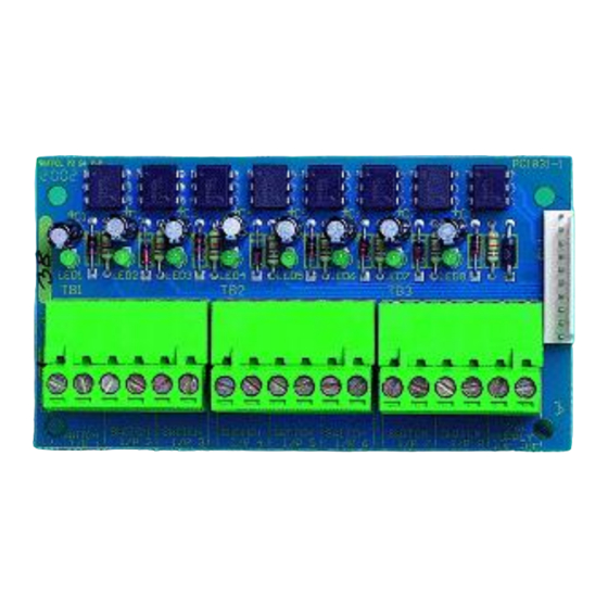
Shop Interface Unit
Features
The Shop Interface Unit allows MxPro 4 control panels to send and receive alarm signals from other
equipment.
Input signals can be received from clean-contact inputs, with two of the inputs also supporting
and short circuit fault monitoring on the external wiring.
A special input is also able to differentiate between an input that is pulsing (ALERT) or is on continuously
(EVAC), allowing easy interfacing to older equipment that cannot provide independent Alert and Evacuate
signals.
Two fully programmable outputs are also provided to allow signals to be transmitted out to other equipment.
The operation and functions described in this manual are available from Software Version 4000-016-00 onwards.
www.acornfiresecurity.com
www.acornfiresecurity.com
open circuit
Advertisement
Table of Contents

Related Manuals for Advanced MxPro 4


Summary of Contents for Advanced MxPro 4
- Page 1 Shop Interface Unit Features The Shop Interface Unit allows MxPro 4 control panels to send and receive alarm signals from other equipment. Input signals can be received from clean-contact inputs, with two of the inputs also supporting open circuit and short circuit fault monitoring on the external wiring.
- Page 2 The Interface is used in place of the standard MXP-014 8-way input board (i.e. don’t attempt to fit both units to the same chassis). Compatibility: The Shop Interface unit mounts in the MxPro 4 panels as follows: Mx-4200, Mx-4400 & Mx-4800 control panels – directly onto the chassis. Mx-4100/L control panel – on the rear face of the back box.
-
Page 3: Table Of Contents
www.acornfiresecurity.com Table of Contents Page INSTALLATION .............................. 4 -029 -4100/L .................... 4 NSTALLING THE IN THE 1.1.1 Mounting the Card ..........................4 1.1.2 Internal Wiring ............................ 4 -029 -4200/M -4400/M -4800 ..............5 NSTALLING THE IN THE ..........................5 OUNTING THE ............................ -
Page 4: Installation
www.acornfiresecurity.com 1 Installation 1.1 Installing the Mxp-029 in the Mx-4100/L 1.1.1 Mounting the Card The card mounts on 4 pillars in the rear of the enclosure. See diagram opposite. Remove the gear tray assembly and set aside in a safe place. Screw in the four spacers supplied into the threaded inserts in the back box. -
Page 5: Installing The Mxp-029 In The Mx-4200/Mx-4400/Mx-4800
www.acornfiresecurity.com 1.2 Installing the Mxp-029 in the Mx-4200/Mx-4400/Mx-4800 1.3 Mounting the Card The card mounts on 4 pillars in the bottom left hand M3 Fixing Screws corner of the control panel chassis adjacent to the Base Card Mx4200 / Mx4400 base card. See Figure 2 opposite. -
Page 6: External Wiring
www.acornfiresecurity.com 1.5 External Wiring Mxp-029 Field wiring connections are shown in the TO DISPLAY diagram opposite. NB: These circuits are classed as Safety Extra Low Voltage (SELV) circuits. Route away from mains wiring. Figure 5 RL1 RL2 Power 10K ¼W Inputs A and B can be monitored for open and short circuit conditions. -
Page 7: Configuration
www.acornfiresecurity.com 2 Configuration Programming can also be performed from the PC configuration program. Shop Interface Input PC Program Inputs Purpose Settings required at PC INPUT A Panel S/W-1 Switch Input Set Zone, Text & Action Panel S/W-2 Cable Fault Set Zone, Text & Action=Fault INPUT B Panel S/W-3 Switch Input... -
Page 8: Programmable Outputs
www.acornfiresecurity.com 2.2 Programmable Outputs Relays 1 and 2 are programmed in the same way as the relays on the MXP-008 8-way relay card. Shop Interface Output PC Program Output Purpose Settings required at PC RELAY 1 Panel O/C-1 Programmable Output Set Text &... - Page 9 www.acornfiresecurity.com USER NOTES www.acornfiresecurity.com...
- Page 10 www.acornfiresecurity.com www.acornfiresecurity.com...
Need help?
Do you have a question about the MxPro 4 and is the answer not in the manual?
Questions and answers