Table of Contents
Advertisement
Quick Links
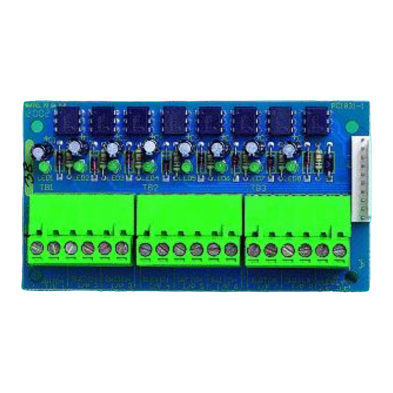
8 Way Input Card
Features
The Mxp-014 is an internal peripheral for use with the MxPro 4 multi-loop panels. The unit provides a cost
effective method of monitoring for up to 8 individual clean contact switch inputs.
Each input can be programmed to generate a specific user defined function from the control panel program
and can be assigned to an individual or common zone. The input functions can be either latched or non-
latched and includes Fire, Fault, Pre-alarm, Security, General Alarm, Group Disable, Control Signal, Level-2
access enable etc. together with any other programmable input option allowed within the MxPro 4 systems
DynamiX zoning facilities.
The unit connects directly to the panel and is ideal for class change or non-latching operation where a fast
input response is essential.
www.advancedco.com
Advertisement
Table of Contents

Related Manuals for Advanced MxPro 4


Summary of Contents for Advanced MxPro 4
-
Page 1: Features
8 Way Input Card Features The Mxp-014 is an internal peripheral for use with the MxPro 4 multi-loop panels. The unit provides a cost effective method of monitoring for up to 8 individual clean contact switch inputs. Each input can be programmed to generate a specific user defined function from the control panel program and can be assigned to an individual or common zone. - Page 2 Specifications & Ordering: Models, Sales Order Parts: Mxp-014: 8 Way Input Card Mxp-014F: 8 Way Input Card fitted within a Mx-4100/L, Mx-4200, Mx-4400 or Mx-4800 control panel Applications / Limitations: All inputs can be individually programmed to any of the specific functions allowed in the control panel programme: i.e.
-
Page 3: Table Of Contents
Table of Contents Page FEATURES ................................1 INSTALLATION .............................. 4 -014 -4100/L .................... 4 NSTALLING THE IN THE 1.1.1 Mounting the Card ..........................4 1.1.2 Internal Wiring ............................ 4 -014 -4200/M -4400/M -4800 ..............4 NSTALLING THE IN THE ..........................4 OUNTING THE ............................ -
Page 4: Installation
1 Installation 1.1 Installing the Mxp-014 in the Mx-4100/L 1.1.1 Mounting the Card The card mounts on 4 pillars in the rear of the enclosure. See diagram opposite. Remove the gear tray assembly and set aside in a safe place. Screw in the four spacers supplied into the threaded inserts in the back box. -
Page 5: Internal Wiring
Figure 3 1.4 Internal Wiring Base Card Cable A 10 way single in line ribbon cable is used to Input Card connect the input card, via the latched header – PL1, to the 10 way latched header on the back of the display card. Route the cable as shown in the diagrams opposite. -
Page 6: External Wiring
1.5 External Wiring The picture below shows the terminal block positions for All electrical wiring installation work should be carried out in accordance with the code of each switch input. practice applicable in the country of installation. Install cables suitable for the application and degree of fire To maintain electrical integrity of the SELV protection required. - Page 7 USER NOTES www.advancedco.com...
- Page 8 Doc Number: 680-031 Revision: Advanced Electronics Ltd Moorland Way, Cramlington, Northumberland, NE23 1WE UK First Issued: 2013-mm-dd Tel: +44 (0)1670 707 111 Fax: +44 (0)1670 707 222 Email: sales@advancedco.com Web: www.advancedco.com www.advancedco.com...
Need help?
Do you have a question about the MxPro 4 and is the answer not in the manual?
Questions and answers